Sony Underwater Housing for Select RX100-Series Cameras User Manual
Page 43
43
A
Number
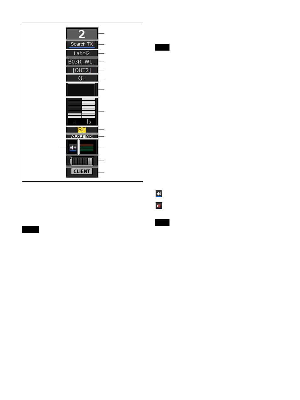
Displays the receiver channel number.
B
Search TX
Makes the screens for transmitters that are paired with the
receiver blink.
• This function is not supported on the DWR-R01D,
DWR-R02D, and DWR-R02DN.
• This function is only available on combinations of 3rd
generation or later digital wireless receivers (such as the
DWR-R03D) and digital wireless transmitters (such as
the DWT-B03R). In addition, when using an RMU-01
for Cross Remote connection, the RMU-01 must be
version 1.27 or later.
C
Label
Displays the label configured in the [Receiver CH Label
settings] window.
D
Transmitter name
Displays the name of the transmitter.
E
Output channel display
Displays the audio output destination of the receiver.
In normal operation, channel 1 is output from OUT 1, and
channel 2 is output from OUT 2.
When the OUTPUT SWAP setting is enabled, channel 1 is
output from OUT 2, and channel 2 is output from OUT 1.
The settings are also highlighted on the display.
OUTPUT SWAP is available only on the DWR-R03D
version 1.20 or later.
F
QL (signal quality level) alert
Lights red when the quality of the received data decreases.
G
QL (signal quality level) meter
Indicates the quality of the received data in a meter.
H
RF (radio wave) level meter
Indicates the radio wave input level according to eight levels.
I
RF (radio wave) level alert
Lights red when the radio wave input level decreases.
When the radio wave input level is high, this lights yellow.
J
AF/PEAK (audio input/peak) alert
Lights red when the level of audio signal input to the transmitter
exceeds the transmitter’s maximum input level setting.
K
Audio output control/indicator
Indicates the status of audio output for the receiver channel.
Clicking the icon toggles the status of audio output.
: Audio output is enabled. Clicking the icon will enable
muting of the audio output.
: Audio output muting is enabled. Clicking the icon
will disable muting of the audio output.
This setting can only be changed if the [Individual muting/
unmuting] checkbox is selected in the [Display settings]
window.
For details, see “[Display settings] Window” on page 56.
L
AF level meter
Indicates the level of the audio signal input to the
transmitter according to four levels.
The way the meter lights will vary depending on the input
level setting of the transmitter.
• When the INPUT LEVEL settings of the transmitter is
MIC level
Unlit
: The input level of the audio signal is less than
–36 dBFs.
1 bar lit
: The input level of the audio signal is –36 dBFs
or more and less than –20 dBFs.
2 bars lit
: The input level of the audio signal is –20 dBFs
or more and less than –3 dBFs.
3 bars lit
: The input level of the audio signal is –3 dBFs
or more.
• When the INPUT LEVEL settings of the transmitter is
LINE level
Notes
1
3
2
4
5
6
7
8
9
0
qd
qf
qs
qa
Note
Note