Pin assignment and connection, Motor feedback connections, Resolver – Pilz Cable PMCprimoDrive>Mod-Profibus:L=0,45m User Manual
Page 29
Operating Manual: PMCtendo AC
7-3
Pin assignment and connection
The sections below describe all the connections on a PMCtendo AC servo motor plus
their layout. The connections that your servo motor actually has at its disposal will
depend on the code stated in the order reference (see section entitled “Overview”).
INFORMATION
Only used shielded cable. Pre-assembled cable in various lengths and cross sections is
available from Pilz.
Motor feedback connections
Resolver
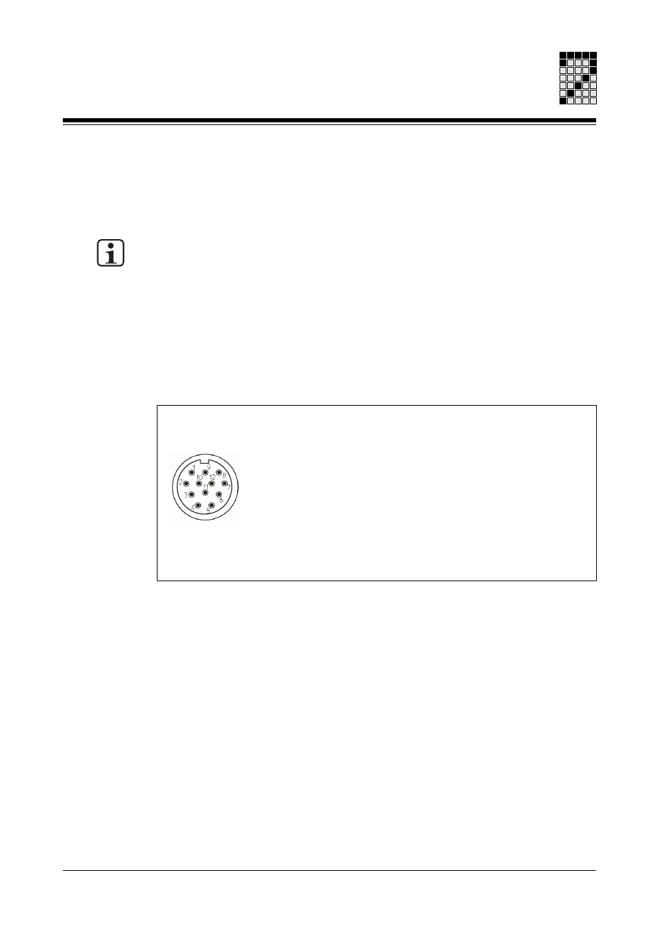
To connect the resolver (see Fig. 7-3) to the servo amplifier you will need a cable with a
layout as shown in Fig. 7-4.
Fig. 7-3: Pin assignment of the round resolver connector
1:
S1 (Cos1)
2:
S2 (Sin1)
3:
S4 (Sin2)
4:
n.c.
5:
n.c.
6:
S3 (Cos2)
Round connector
12-pin, male
7:
R1 (Ref1)
8:
Internal shield
9:
Thermal switch
10:
Thermal switch
11:
R2 (Ref2)
12:
n.c.
n.c. = not connected