Nexen TC920V 964356 User Manual
Page 12
9
FORM NO. L21268-C-1013
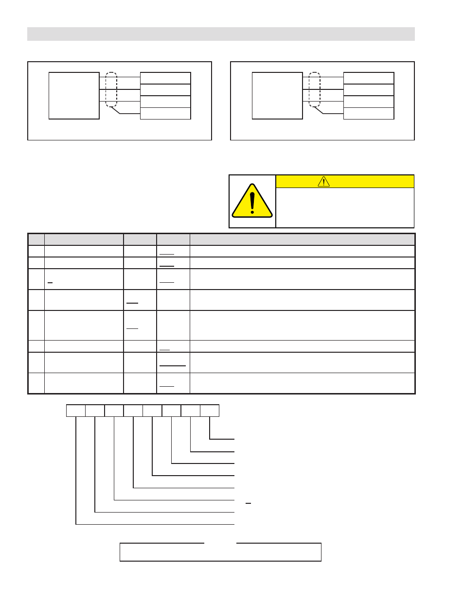
3.3.4 e
nCoDer
C
onneCtion
3.3.5 P
roximity
S
enSor
C
onneCtion
3.4 SETTING BASIC OPERATING MODE - DIP SWITCH (SW1)
FIGURE 3.12 Encoder Wiring Diagram
FIGURE 3.13 Proximity Sensor Wiring Diagram
The DIP switch (SW1) located on the backside of the front
panel sets the basic operation mode of the TC920V. For
most applications, these switch settings will not require
adjustment except during the calibration process. Refer
to Section 2.2 for details on accessing the Main Board for
setting SW1.
CAUTION
Set the DIP Switch (SW1) only when the
unit is powered OFF except for SW1-8.
# Function
ON
OFF
Description
1 Internal Use
OFF
For Internal Use Only. Leave in the OFF position.
2 Separate Mode
ON
OFF
Leave in the OFF position.
3 +Output
ON
OFF
Sets control output for 0-10V to ±10V output. Not for use with 4-20mA
output.
4 English Indication
ON
OFF
Leave in the ON position for English display on the front panel LCD,
OFF position for Japanese.
5 Diameter Gain Control ON
OFF
Normally adjust gain based on output level for Wind/Unwind ap-
plications with changing diameter. Turn off for mid process tension
zones where diameter remains constant.
6 Unit of Tension
N
lbF
Select the Unit of Tension to be displayed on the LCD.
7 Control Direction
Reverse Forward
In forward mode, as the control output increases the system tension
also increases. Select reverse for the opposite action.
8 Calibration Mode
ON
OFF
Set to the ON position for zero/span adjustment. Refer to Section
5 for details.
1
2
3
4
5
6
7
8
8: Calibration Mode
7: Control Direction
6: Unit of Tension
5: Diameter Gain Control
4: English Indication
3: +Output
2: Separate Mode
1: Internal Use
ON Side
OFF Side
NOTE
The underline indicates a position set at the factory.
3. INSTALLATION (continued...)
23
24
25
26
23
21
22
26
R
BN
BK
BN
B
BK
Encoder
Proximity
Sensor