Advanced settings (continued...) – Nexen TC920V 964356 User Manual
Page 28
25
FORM NO. L21268-C-1013
7. ADVANCED SETTINGS (continued...)
7.2
ACCELERATION/DECELERATION CORRECTION
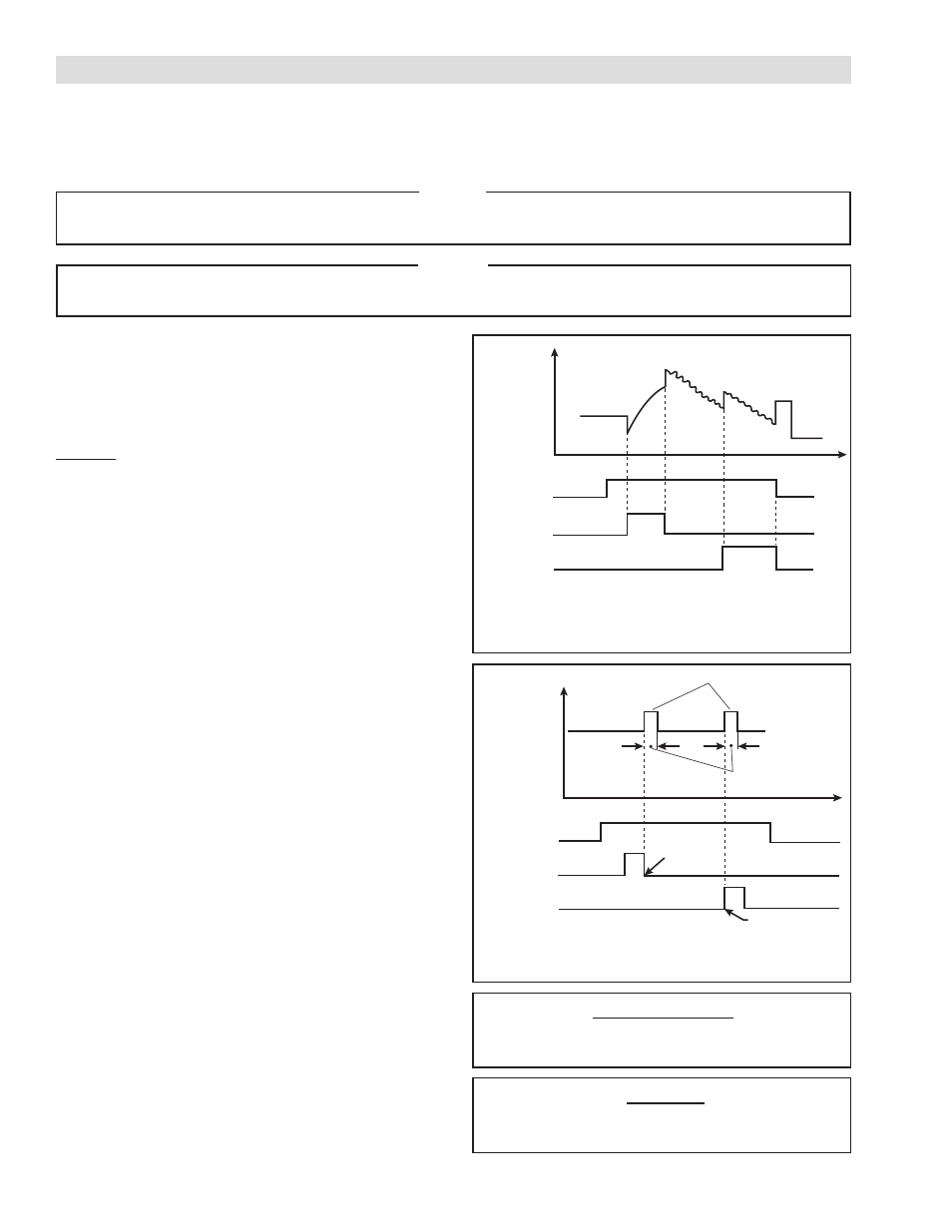
FIGURE 7.1
Correction Sequence Diagram of Mode 1
FIGURE 7.2
Correction Sequence Diagram of Mode 2
Equation 7.1 Mode 1 Correction
Equation 7.2 Mode 2 Correction
Correction Value =
• Correction Factor
Previous Control Output Value
100
Correction Value =
• Correction Factor
Tension Setpoint
100
This mode allows for the compensation of large roll inertia during machine acceleration and deceleration by applying ad-
ditional gain. This can help prevent slackness in the web at the end of acceleration or the start of deceleration.
NOTE
The Software DIP Switch MSW0–1 and –2 must be set to “ACEL” to function as the deceleration
compensation for Mode 1 & 2.
• No. 28 Correction Time
(Applies to Mode 2)
• MSW0-1, 2 (Set to ACEL) (Required in Mode 1 & 2)
• No. 44 Correction Mode
• No. 27 Correction Factor (Applies to Mode 1 & 2)
Mode 0: Tension Deviation Polarity Gain Correction
Correction is performed by applying different gain depend-
ing on the polarity of the tension deviation to increase
responsiveness. The same contact is used for both accel-
eration & deceleration Terminals 6 & 12 . Refer to section
7.4.2 for setting the correction gains.
Mode 1: Direct Compensation (for unwind brake)
In this mode, the Correction Factor bias is applied directly
to the output for the duration of the Acceleration / Decel-
eration period. The acceleration and deceleration contacts
are separate. The deceleration contact uses Terminals 6 &
12 while the acceleration contact uses Terminals 8 & 12.
During machine acceleration and deceleration, the cor-
responding contact should be turn ON for the duration of
the acceleration or deceleration period.
When accelerating, bias is applied so that the final output
is reduced by the compensation level. During deceleration,
the bias is applied so that the final output is increased by
the compensation level. The compensated control output
can be calculated from Equation 7.1.
Mode 2: Setpoint Correction
In this mode, the correction is added directly to the setpoint
to respond to slackness faster. This operation is performed
at the end of acceleration and the start of deceleration for
the duration of Correction Time and then returned to the
initial tension setpoint. The acceleration and deceleration
contacts are separate. The deceleration contact uses Ter-
minals 6 & 12 while the acceleration contact uses Terminals
8 & 12. The compensated setpoint can be calculated from
Equation 7.2.
Control Output
ON
ON
ON
Automatic
Contact
Contact at
Acceleration
Contact at
Deceleration
Set tension
At the start of
deceleration
Increased setting
Correction time
Automatic
Contact
Contact at
Acceleration
Contact at
Deceleration
At the end of
acceleration
NOTE
For advanced users only.
Best recommendation is to use the default value and only change if absolutely necessary.