Altera MAX 10 Embedded Multipliers User Manual
Page 28
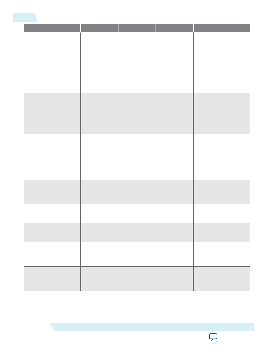
GUI Parameter
Parameter
Condition
Value
Description
What is the source for
asynchronous clear
input?
OUTPUT_ACLR • Outputs
Configuration
> Register
output of the
adder unit =
On
• Outputs
Configuration
> More
Options
• Aclr0–Aclr2
• None
Specifies the source for
asynchronous clear
input.
What operation should
be performed on
outputs of the first pair
of multipliers?
MUTIPLIER1_
DIRECTION
General > What
is the number of
multipliers? = 2,
3, or 4
• Add
• Subtract
• Variable
Specifies whether the
second multiplier adds
or subtracts its value
from the sum. Values
are add and subtract. If
Variable is selected the
addnsub1
port is used.
‘
addnsub1
’ input
controls the operation
(1 add/0 sub)
—
Adder Operation
> What
operation should
be performed on
outputs of the
first pair of
multipliers? =
Variable
More Options
High ‘
addnsub1
’ input
indicates add and low
‘
addnsub1
’ input
indicates subtract.
Register ‘
addnsub1
'
input
—
—
On or Off
Turn on this option if
you want to enable the
register of ‘
addnsub1
’
input
Add an extra pipeline
register
—
—
On or Off
Turn on this option if
you want to enable the
extra pipeline register
Input Register > What
is the source for clock
input?
ADDNSUB_
MULTIPLIER_
REGISTER[1]
Adder Operation
> More Options
Clock0–Clock3
Specifies the source for
clock input.
Input Register > What
is the source for
asynchronous clear
input?
ADDSUB_
MULTIPLIER_
ACLR[1]
Adder Operation
> More Options
• Aclr0–Aclr2
• None
Specifies the source for
asynchronous clear
input.
Pipeline Register >
What is the source for
clock input?
ADDNSUB_
MULTIPLIER_
PIPELINE_
REGISTER[1]
Adder Operation
> More Options
Clock0–Clock3
Specifies the source for
clock input.
6-4
ALTMULT_ADD Parameter Settings
UG-M10DSP
2014.09.22
Altera Corporation
ALTMULT_ADD (Multiply-Adder) IP Core References