Figure 2–8 – Altera RAM Initializer User Manual
Page 25
Altera Corporation
Confidential—Internal Use Only
2–13
May 2008
RAM Initializer (ALTMEM_INIT) Megafunction User Guide
Getting Started
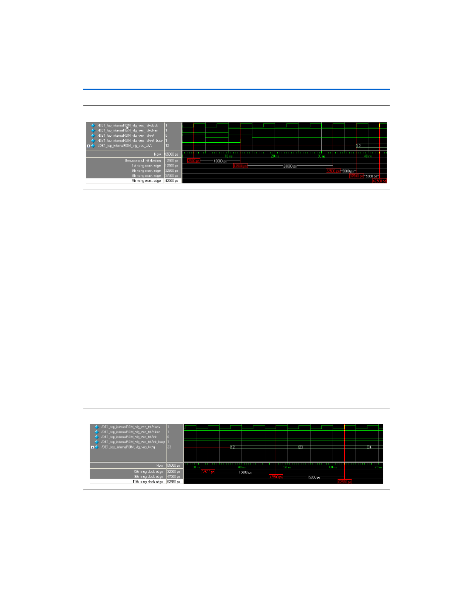
Figure 2–8. Design Example 1: Asserting the init Signal
At 2500 ps, the init signal is high, but initialization is unsuccessful
because the clken signal is low. The initialization process can be
activated only when both the clken and init signals are high at the
rising edge of the clock.
At 12,500 ps, both the clken and init signals are high; therefore,
initialization is activated. After initialization is activated, the init_busy
signal is asserted to indicate that initialization is in progress.
1
Consider the time when initialization is activated as the first
rising edge of the clock.
After the initialization is activated, the first value, 0x12, is written into the
RAM at the fifth rising edge of the clock. The value then appears at the
output port of the RAM at the sixth rising edge of the clock. The
ALTMEM_INIT megafunction takes 4 clock cycles to write the first value
into the device RAM—3 clock cycles to generate and 1 clock cycle to write
the value. The device RAM then takes 1 clock cycle to write the value to
its output port, q. In total, the output of the first value is delayed by
5 clock cycles upon assertion of the init signal.
shows the delay cycles of the first write process and
subsequent write processes after the init signal is asserted.
Figure 2–9. Design Example 1: Delay Cycles of First Write Process and Subsequent Write Processes