Autolink setup, Autolink start and stop, Autolink setup –5 autolink start and stop –5 – Altera Transceiver Signal Integrity User Manual
Page 23
Chapter 6: Stratix IV GX Transceiver Signal Integrity Demonstration
6–5
Running the Demonstration Application and Test Designs
December 2011
Altera Corporation
Transceiver Signal Integrity Development Kit,
Stratix IV GX Edition User Guide
In the signal_integrity_demo1.sof, internal serial loopback is not enabled for the two
channels configured in PCI Express (PIPE) mode. Therefore, you must connect an
external SMA cable between the transmit output and the receive input to loopback the
data.
Autolink Setup
This feature provides the following options:
1
The receiver data checker must be active to determine whether the settings attempted
by the hardware are successful. Therefore, you must connect the transmitter output to
the receiver input through external cable.
If you are evaluating the characteristic of a third party upstream transmitter
connected to the Stratix IV GX receiver, you must supply the appropriate data pattern
as selected in the application, for the data checker to determine the BER for a given
setting.
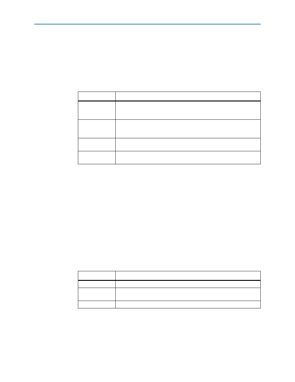
Autolink Start and Stop
Selecting the start option enables the hardware to perform the operation specified in
Autolink setup
. After this setup is complete, the stop field gets highlighted in green
or red. Set the stop field and record the converged settings. The following explains the
color coding of the stop field:
The DataChk Status field also shows whether the hardware is in progress, done
(successful), or no setting (failure) status.
Table 6–3.
Parameter
Description
Manual
You can manually change the preemphasis and equalization to observe the
setting that provides an error free link. For more information about
DataChk Status, refer to
“Link Statistics Tab” on page 6–6
PEandEQ
When you select this option and the start button, the hardware finds a
preemphasis and equalization setting that meets the bit-error rate (BER) of
10–12.
EQonly
When you select this option and the start button, the hardware finds an
equalization setting that meets the BER of 10–12.
PEonly
When you select this option and the start button, the hardware finds the
preemphasis settings (pre tap and 1stpost tap) to obtain an error free link.
Table 6–4.
Color Code
Description
green
the hardware successfully finds the settings that give an error free link.
red
if the hardware is not able to find the settings, it provides the setting that
yielded the least number of errors.
yellow
the hardware is finding the PMA settings.