Altera Arria V GX FPGA Development Board User Manual
Page 30
2–20
Chapter 2: Board Components
Configuration, Status, and Setup Elements
Arria V GX FPGA Development Board
November 2013
Altera Corporation
Reference Manual
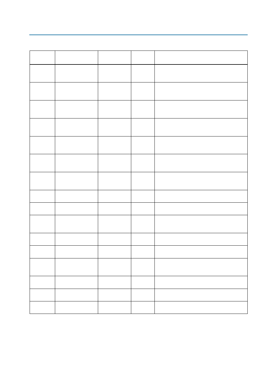
D34
DEVICE1_LED
—
2.5-V
Green LED. Illuminates when FPGA 1 is
successfully configured. Driven by the MAX II
CPLD EPM2210 System Controller.
D35
DEVICE2_LED
—
2.5-V
Green LED. Illuminates when FPGA 2 is
successfully configured. Driven by the MAX II
CPLD EPM2210 System Controller.
D36
ENET_LED_TX
—
2.5-V
Green LED. Illuminates to indicate Ethernet PHY
transmit activity. Driven by the Marvell 88E1111
PHY.
D37
ENET_LED_RX
—
2.5-V
Green LED. Illuminates to indicate Ethernet PHY
receive activity. Driven by the Marvell 88E1111
PHY.
D40
ENET_LED_LINK10
—
2.5-V
Green LED. Illuminates to indicate Ethernet linked
at 10 Mbps connection speed. Driven by the
Marvell 88E1111 PHY.
D38
ENET_LED_LINK100
—
2.5-V
Green LED. Illuminates to indicate Ethernet linked
at 100 Mbps connection speed. Driven by the
Marvell 88E1111 PHY.
D39
ENET_LED_LINK1000
AN17
2.5-V
Green LED. Illuminates to indicate Ethernet linked
at 1000 Mbps connection speed. Driven by the
Marvell 88E1111 PHY.
D4
HSMA_RX_LED
AT15
2.5-V
Green LED. Illuminates to indicate HSMA port A
receive data activity.
D5
HSMA_TX_LED
AH14
2.5-V
Green LED. Illuminates to indicate HSMA port A
transmit data activity.
D6
HSMA_PRSNTn
AW15
3.3-V
Green LED. Illuminates when HSMC port A has a
board or cable plugged-in such that pin 160
becomes grounded. Driven by the add-in card.
D7
HSMB_RX_LED
AG26
2.5-V
Green LED. Illuminates to indicate HSMA port B
receive data activity.
D8
HSMB_TX_LED
AM28
2.5-V
Green LED. Illuminates to indicate HSMA port B
transmit data activity.
D9
HSMB_PRSNTn
AT24
3.3-V
Green LED. Illuminates when HSMC port B has a
board or cable plugged-in such that pin 160
becomes grounded. Driven by the add-in card.
D44
PCIE_LED_X1
AC18
2.5-V
Yellow LED. Configure this LED to display the PCI
Express link width x1.
D43
PCIE_LED_X4
AD17
2.5-V
Yellow LED. Configure this LED to display the PCI
Express link width x4.
D42
PCIE_LED_X8
AT16
2.5-V
Yellow LED. Configure this LED to display the PCI
Express link width x8.
Table 2–9. Board-Specific LEDs (Part 2 of 2)
Board
Reference
Schematic Signal
Name
Arria V GX FPGA
Pin Number
I/O
Standard
Description