Altera Cyclone III FPGA Starter Board User Manual
Page 12
2–4
Altera Corporation
Cyclone III FPGA Starter Board Reference Manual
April 2012
Board Overview
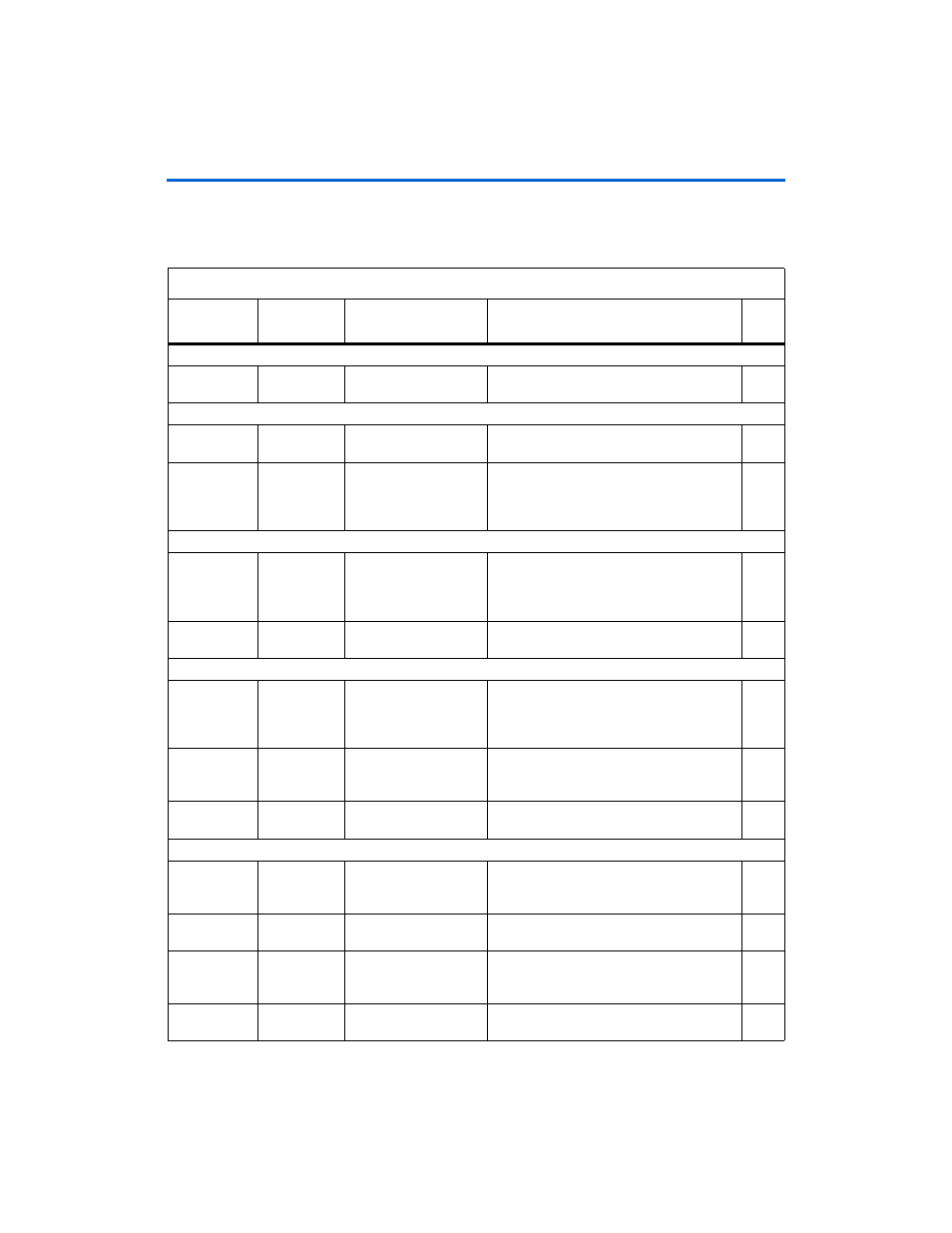
Table 2–1
describes the components and lists their corresponding board
references.
Table 2–1. Cyclone III FPGA Starter Board (Part 1 of 2)
Type
Component/
Interface
Board Reference
Description
Page
Featured Device
FPGA
Cyclone III
device
U1
EP3C25F324-C8, 324-pin FBGA package
User Interfaces
I/O
Push-button
switches
Button1–Button4, CPU
Reset, Reconfigure
Four push-button switches for user-defined,
logic inputs.
I/O
LEDs
LED1–LED4,
Conf_Done, Link,
Power, Flash_CEN,
Load
Four user-defined LEDs
Connections & Interfaces
I/O
USB UART
U8
USB interface to the Cyclone III device for
external FPGA configuration and
communication with applications running on
the FPGA.
Input
HSMC
Connector
J1
Header for connecting the HSMC interface.
Configuration & Reset
Input
JTAG header
J4
Jumper header to select which JTAG source
the board uses, for example, the JTAG
header configuration or the USB JTAG
configuration.
Input
USB
connector
J3
Type B USB Connector that allows for
connecting a Type A-B USB cable between a
PC and the board.
Display
Configuration
done LED
Conf_Done
LED that illuminates when FPGA is
successfully configured.
Memory
Flash
16-MB
parallel flash
memory
U6
16 MB of non-volatile memory.
2–13
Display
Flash LED
LED that illuminates when the flash is being
accessed.
N/A
SSRAM
1-MB
high-speed
SSRAM
U5
256K x 32 synchronous SRAM
2–17
DDR SDRAM
32-MB DDR
SDRAM
U4
4M x16 x 4 DDR SDRAM
2–15