Push-buttons – Altera Cyclone III FPGA Starter Board User Manual
Page 19
Altera Corporation
2–11
April 2012
Cyclone III FPGA Starter Board Reference Manual
Board Components and Interfaces
Push-Buttons
The board has system reset, user reset, and user push-buttons.
lists the pinout for all push-buttons. The push-buttons are in logic “1”
until depressed.
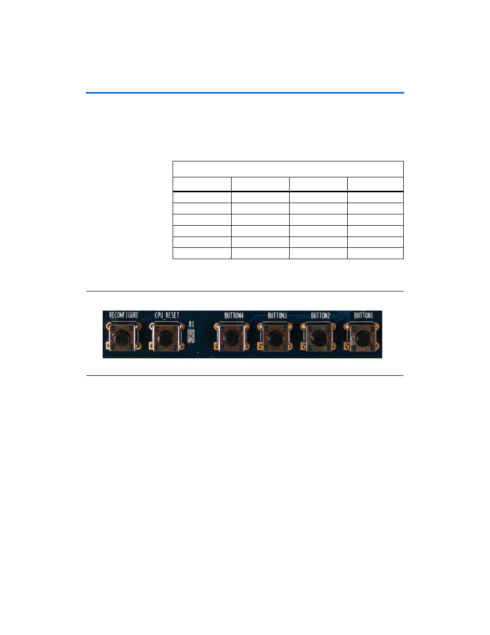
shows the push-buttons.
Figure 2–5. Push-Buttons
System Reset Push-Buttons
The system reset push-button starts a reconfiguration of the FPGA from
flash memory.
User Reset Push-Buttons
The user reset push-button is an input to the Cyclone III device. This
push-button is intended to be the master reset signal for the FPGA
designs loaded into the Cyclone III device. The user reset push-button is
connected to the DEV_CLRn pin on the FPGA. The DEV_CLRn setting is a
pin option in the Quartus II software that you must enable to function as
DEV_CLRn
instead of a standard I/O.
Table 2–9. Push-Button Pinout
Signal Name
FPGA Pin
Direction
Type
KEY0
F1
Input
2.5 V
KEY1
F2 Input
2.5 V
KEY2
A10 Input
2.5 V
KEY3
B10 Input
2.5 V
CPU_RESET_N
N2
Input
2.5 V
RECONFIGURE
H5 (nConfig)
Input
2.5 V