Trailer power supply, Bulb failure indicator for led lamps, Trailer with 7-pin connector – Mercedes-Benz 2012 A Class User Manual
Page 208: Driving and parking, Towing a trailer
X
Press the ball coupling in the direction of
the arrow until it engages behind the
bumper.
Indicator lamp ? goes out and the mes-
sage in the multifunction display disap-
pears.
Trailer power supply
!
You can connect accessories with a
power rating of up to 240 W to the perma-
nent power supply and with a power rating
of up to 180 W to the power supply that is
switched on via the ignition lock.
The trailer battery may not be charged from
the power supply.
X
To switch the connected power supply
on or off: turn the key in the ignition lock
to position
2 or 0 respectively.
When it leaves the factory, your vehicle's
trailer socket is equipped with a permanent
power supply and a power supply that is
switched on via the ignition lock.
The permanent power supply is supplied via
trailer socket pin 9.
The power supply that is switched on via the
ignition lock is supplied via trailer socket pin
10.
The trailer's permanent power supply is
switched off in the event of low vehicle supply
voltage and after six hours at the latest.
You can find more information about instal-
ling the trailer electrics at a qualified special-
ist workshop.
Bulb failure indicator for LED lamps
i
If LED lamps are fitted in the trailer, an
error message may appear in the multi-
function display even if there is no fault. The
reason for the error message could be that
the current has fallen below the minimum
of 50 mA.
To ensure reliable operation of the bulb failure
indicator, each LED chain in the trailer lighting
must be guaranteed a minimum current of
50 mA.
Trailer with 7-pin connector
General notes
Trailer with 7-pin connector: you can con-
nect to the 13-pin socket on the ball coupling
using an adapter or, if necessary, an adapter
cable. Both can be obtained at a qualified
specialist workshop.
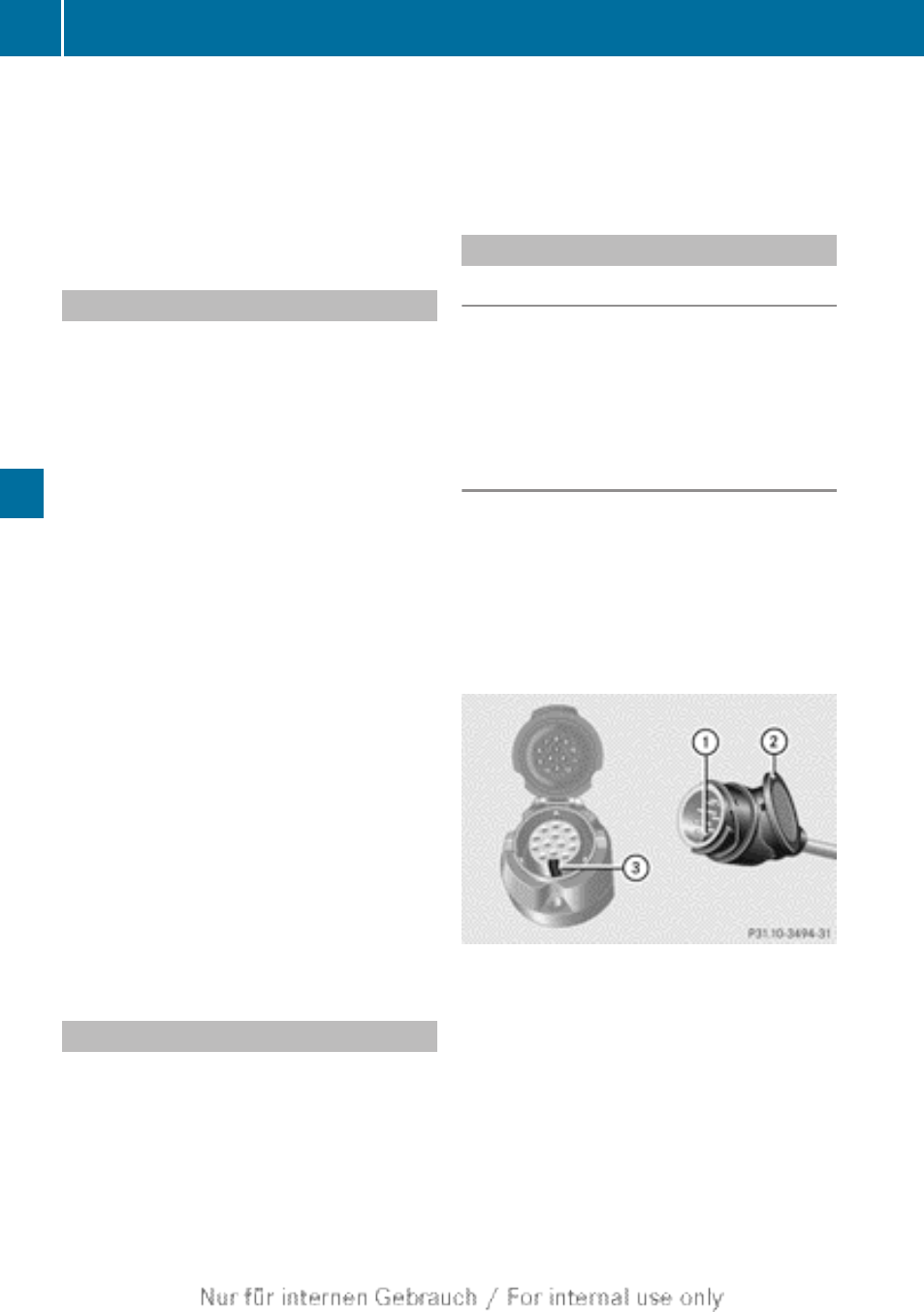
Fitting the adapter
!
Make sure that there is sufficient cable
play so that the cable cannot become
detached when cornering.
!
Remove the installed adapter cable
before folding in the ball coupling. Other-
wise, damage may occur to the rear
bumper and the adapter cable.
X
Open the socket cover.
X
Insert the plug connector with lug : into
groove = on the socket. Turn bayonet con-
nection ; clockwise to the stop.
X
Let the cover engage.
X
If you are using an adapter cable, secure
the cable to the trailer with cable ties.
206
Towing a trailer
Driving and parking