ABUS Technologies Log Box-DA Data Logger User Manual
Page 10
ABUS TECHNOLOGIES INC.
10
Log Box-DA
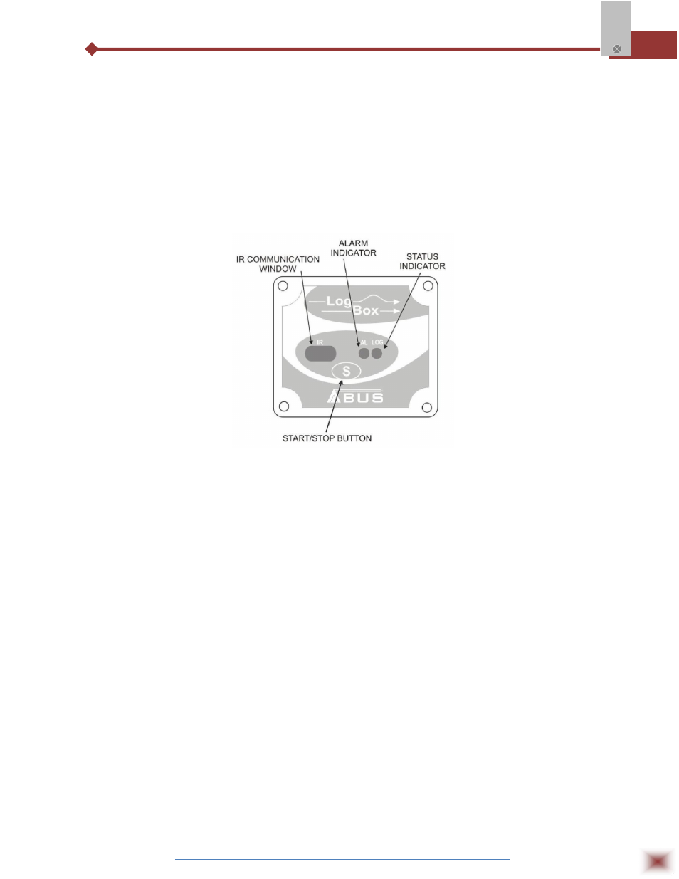
5.2 Panel
The Status Indicators (see Figure LED Indicators and IR communication) are located in the logger
front panel. They indicate the current working conditions of the unit.
LOG Indicator (Logging): While in stand-by (not logging) or after a series of acquisitions is ended, it
flashes once at every four seconds. While logging is active, it flashes twice
every four seconds.
ALM Indicator (alarm): Alerts the user regarding alarm conditions. Once triggered, the alarm LED
keeps flashing once at every four seconds until a new configuration is
entered.
LED Indicators and IR communication
CHANNEL 1 MULTIPLICATION FACTOR
Channel 1 was designed to count electric pulses from liquid flow meters (litters per pulse, for
example). The amount of liquid corresponding to each pulse and the unit of flow can be easily
configured.
Although suited to flow measurements, channel 1 can measure any variable whose signal is an
electric pulse (energy, production batches, etc). The user can define a new unit by typing it in the
corresponding text box. The expression l/pulse in the multiplication factor is meaningless in this case,
so please disregard it.
5.3 LogChart-II
5.3.1 INSTALLING LOGCHART-II
The LogChart II is the software provided with the logger to allow for configuration and data
collection. To install the LogChart II, execute the LC_II_Setup.exe program provided in the CD. The
installation wizard will then guide you throughout the installation process.
Note: Be sure your Windows date separator is configured as a slash: dd/mm/yy or dd/mm/yyyy.
5.3.2 RUNNING LOGCHART-II
Start the program. The main window will appear on the screen, as shown in Figure below.