Connections – ABUS Technologies Log Box-DA Data Logger User Manual
Page 6
ABUS TECHNOLOGIES INC.
6
Log Box-DA
4. CONNECTIONS
Only the input connections and the External Battery Switch (when used) are
needed. The logger is exclusively powered by its internal battery. In the IP65 models,
the inputs and the signal for activating the external power supply are located inside the
logger case, which must be opened for accomplishing the connections. In the IP67
and IP68 models, proper connectors are provided for this purpose, as shown in Figure
IP67/IP68 connectors, below.
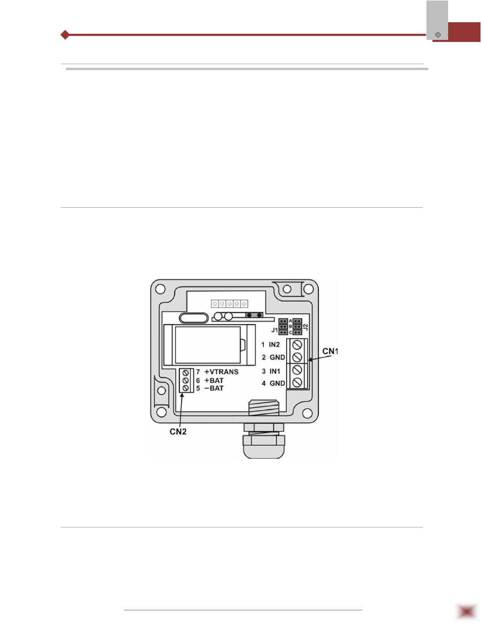
4.1 IP65 Model
Open the logger’s cover to get access to the block terminals and the configuration jumpers.
Connection cables must pass through the compress fitting located at the bottom of the case. Figure
IP65 connections internal view, below indicates signal polarity.
IP65 connections internal view
Note: Make sure that the compress fitting is perfectly tightening the cables, thus assuring proper IP65
protection: (totally dust-tight and protected against water jets).
4.2 IP67/IP68 Model
In theIP67/IP68 version, a M8 connector is provided for signal input, as in Figure 9. When
required, a second M8 connector can be installed to output the signal for commanding the external
power supply. The cables are supplied with the logger.