ABUS Technologies Log Box-DA Data Logger User Manual
Page 8
ABUS TECHNOLOGIES INC.
8
Log Box-DA
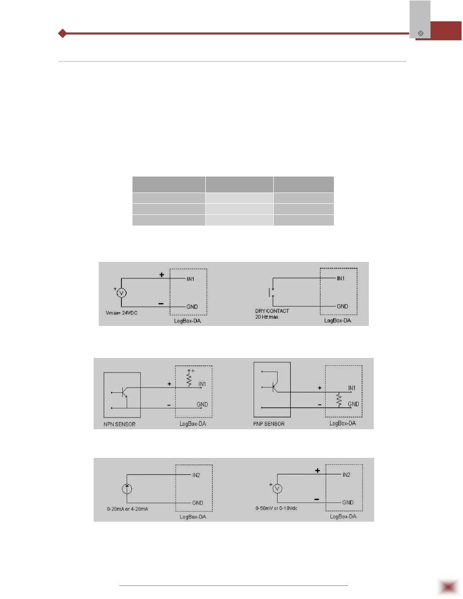
4.3 Input Connections
4.3.1 INPUT CONNECTIONS – CHANNEL 1
The following figures show connections for the various input types accepted in channel 1. No
jumper is required to adjust the channel 1 input type (the circuit is reconfigured automatically according
to the input type selected).
4.3.2 INPUT CONNECTIONS – CHANNEL 2
For adequate use of channel 2, set internal J1 and J2 positioning according to the input signal
chosen, as shown in the table below (factory default is 4-20mA / 0-20mA signals).
INPUT SIGNAL
J1 POSITION
J2 POSITION
4-20 mA / 0-20 mA
A
A
0-10V
B
B
0-50 mV
C
C
J1 and J2 positioning
The following figures show connections for different types of signals applied to channel 2.
Voltage pulse and dry contact channel 1 input
NPN and PNP open collector input for channel 1
Current and voltage inputs for channel 2