Dimensions – ABUS Technologies Log Box-DA Data Logger User Manual
Page 5
ABUS TECHNOLOGIES INC.
5
Log Box-DA
2.2 Memory Capacity
Two memory storage capacities are offered: 32K or 64K records:
32k Model:
Allows up to 32,000 records;
64k Model:
Allows up to 64,000 records;
Memory capacity is always shared between enabled channels. In case there are two channels
enabled, each gets 50 percent of the memory available. When only a single channel is enabled, it has
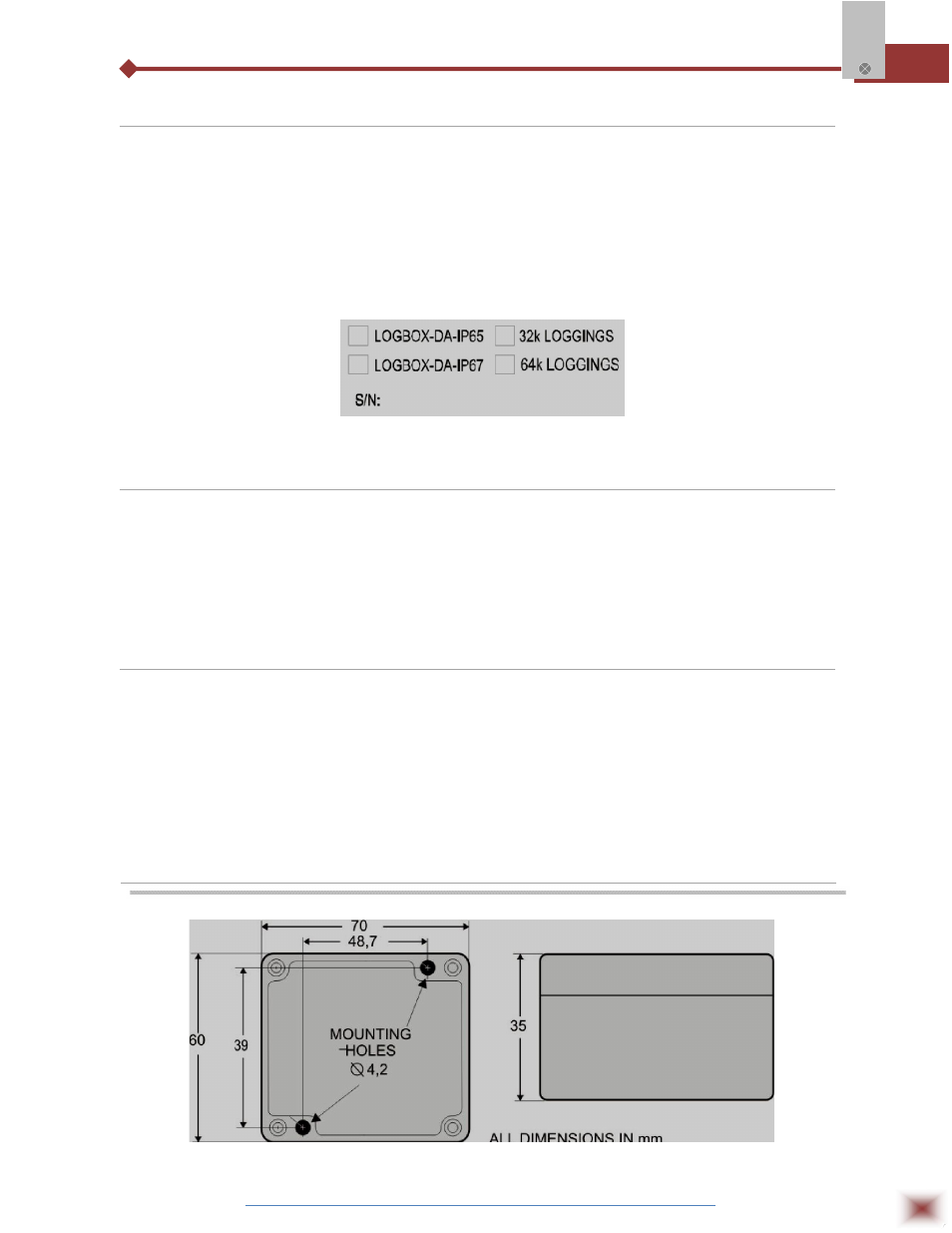
the entire memory at its disposal. Memory capacity is indicated on the identification label placed on the
logger case.
Lateral Identification label
2.3 Input Signals
Channel 1 (IN 1) counts electric pulse signals. They can be voltage pulses, a dry contact
(switch) or open collector signals, as selected in the configuration.
Channel 2 (IN 2) measures linear analog signals, which can be 0-20mA, 4-20mA, 0-50mV or 0-
5V, user defined.
Note: For the channel 2, depending on the input signal selected, it may be necessary to configure an
internal jumper.
2.4 Data Acquisition (logging)
Data can be acquired by means of two different modes.
In channel 1, which counts pulses, the number of input pulses counted in the logging time
interval is stored in the logger memory at the end of the interval. The maximum number of loggings that
can be stored depends on the memory capacity of the device model.
In channel 2, specific for analog signals, the logger can be configured to perform a single
measurement at the end of the selected time interval storing the value read; 10 measurements within
the time interval and store the mean of values read, or, yet, record the minimum or maximum values
read in the interval.
3. DIMENSIONS