2 display – Casella CEL CEL-278 User Manual
Page 11
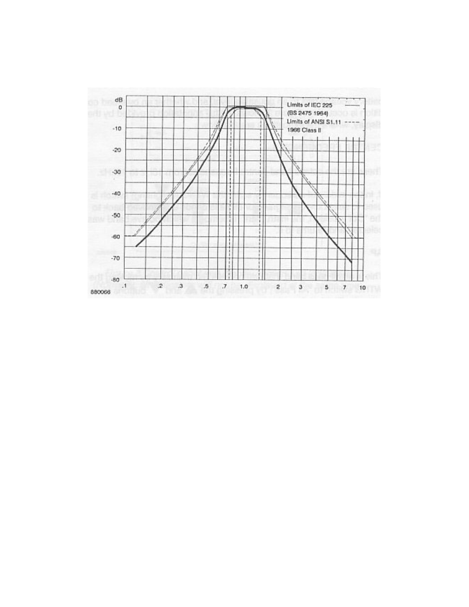
Figure 2 Typical octave filter response curve
pressed, or band step control signals are received via the bottom connector
from an external device such as a level recorder, the logic unit controls the
clock oscillator to step the centre frequency of the filter band. The selected
band centre frequency will be identified by the display.
3.2 Display
As in normal operation the CEL-278/2 Filter Set will be used close coupled to
a CEL sound level meter, the viewing angle of the display has been selected
to give the optimum clarity and legibility when the Instrument is held slightly
away from the Operator's body as required by the relevant measurement
standards, or when fitted to the CEL-4627 Tripod.
Markers on the display adjacent to legends on the bezel identify the filter
centre frequency currently in use. An indication is also given if the
CEL Instruments Ltd.
CEL-278/2 Handbook
Page 11