Installation – CIRCUTOR DHB Series User Manual
Page 8
Advertising
8
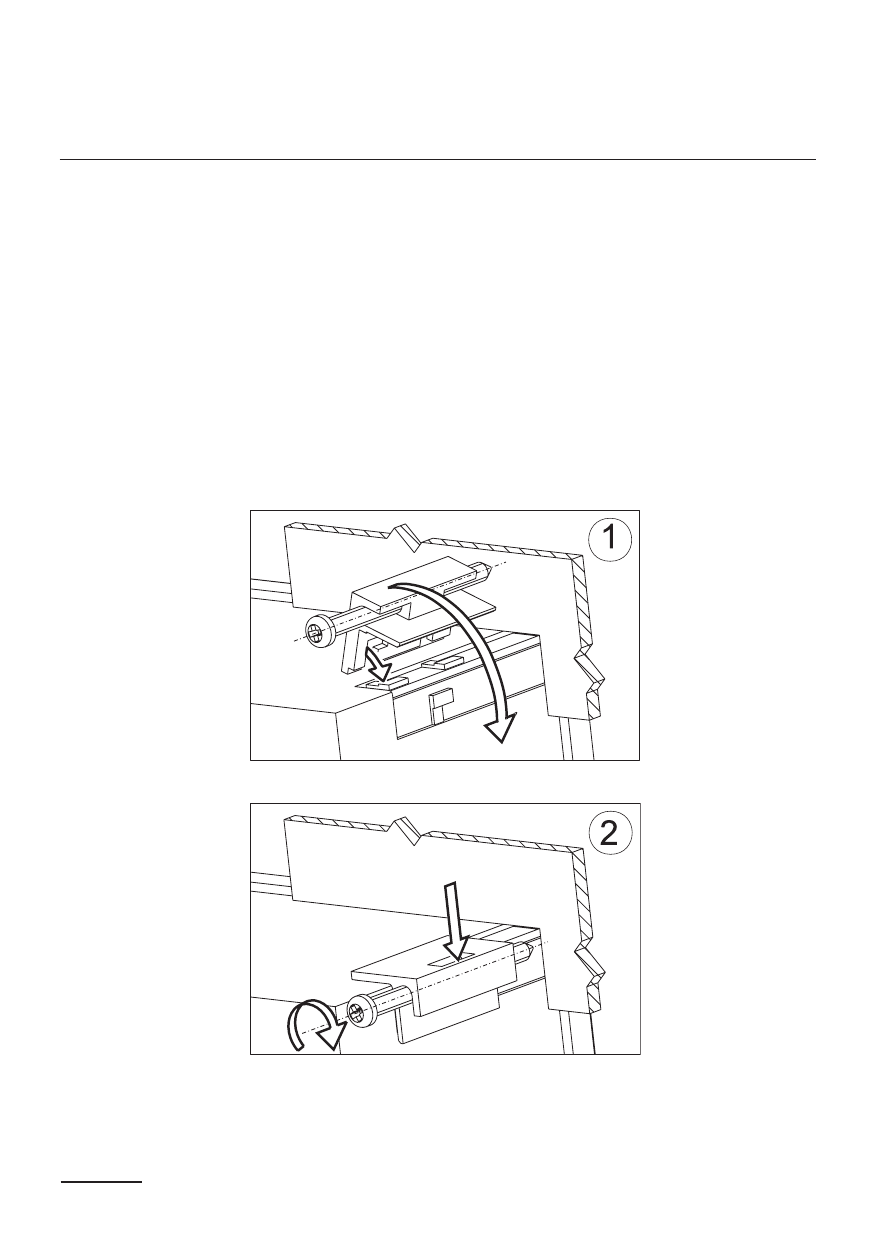
Fig. 2. Meter fixing
User’s Manual.
4. INSTALLATION
The meter has separable strips with screw terminals which enable the
connection of external wires of 2.5 mm
2
cross-section. In execution for
current measurement, the plug enables a permanent fixing to the so-
cket by means of screws.
The meter is adapted to be mounted in a panel by means of clamps,
acc. to the fig. 2. One must prepare a hole of 92
+0.6
´ 45
+0.6
mm in the
panel which the thickness should not exceed 15 mm.
The meter must be introduced from the panel front with disconnected
supply voltage. Before the insertion into the panel, one must check the
correct placement of the seal. After the insertion into the hole, fix the
Advertising