Figure 4 – CIRCUTOR OPTIM HYB Series User Manual
Page 11
Any modification to the regulator connections must be performed exclusively
by
CIRCUTOR personnel or by those properly trained in its use
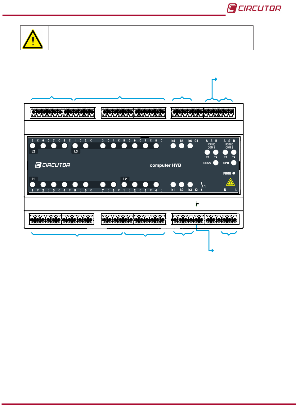
The regulator's input and output terminals are shown in
.
5 C 6
7
8
1
2
C
C
C
C
C
3 C 4
5
6
7
8
C
C
C
C
C
1 C 2
3
4
5
6
C
C
C
C
C
7 C 8
1
2
3
4
C
C
C
C
C
K4 k5 k6
S
C1
A
B
S
A
B
L2
L1
L2
L3
K1 k2 k3 C1
L
N
OUTPUTS 1 AND 8 PANEL CONTROL CPC4
SINGLE-PHASE STAGES L1
COM1 COM2
OUTPUTS 1 AND 4
SINGLE-PHASE STAGES L2
PANEL CONTROL CPC4
OUTPUTS 1 AND 3
CONTACTORS
CONTROL
SUPPLY
POWER
INPUT SIGNAL
NC THERMAL RELAY
OUTPUTS 5 AND 8
SINGLE-PHASE STAGES L2
PANEL CONTROL CPC4
OUTPUTS 1 AND 8 PANEL CONTROL CPC4
SINGLE-PHASE STAGES L3
OUTPUTS 1 AND 3
CONTACTORS
CONTROL
SIGNAL INPUT RS485
FROM CVM-MINI-RS485
AUXILIAR SIGNAL
INPUT RS485
Figure 4: Terminals on the Computer HYB Hybrid Regulator.
2.1.1.2. Indicator LEDs on the Computer HYB regulator.
The
Computer HYB regulator has a series of LEDs on its front panel to indicate the connected
stages, CPU operation, communication status with the CVM-MINI-RS485 and alarm signalling.
The different LEDs on the
Computer HYB front panel are shown in
11
Instruction Manual
OPTIM HYB Series