Red carga, Batería de condensadores – CIRCUTOR OPTIM HYB Series User Manual
Page 25
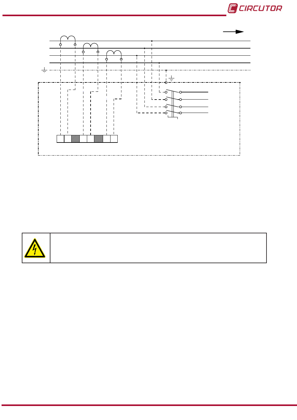
L1
L2
L3
N
RED
CARGA
3x400 V / 1x230 V - 50 Hz
L1
L2
L3
S1
N
TB1
BATERÍA DE
CONDENSADORES
1S1 1S2
S1
S2
S1
S2
S1
S2
T.I.1
T.I.2
T.I.3
2S1 2S2
3S1 3S2
Figure 17: Connection of 3 current transformers (CT) to the OPTIM HYB capacitor bank.
8.- Once the OPTYM HYB capacitor bank and the current transformers are connected, discon-
nect the panel by opening the general quadrupole switch inside the capacitor bank (OFF posi-
tion) and check that the LEDs of the
Computer HYB regulator turn off, indicating no voltage.
Then close (put in I position, with the lever in up position)
all the protection circuit breakers
on the power circuit, including the three-pole circuit breakers on the three-phase stages and
the unipolar circuit breakers on the single-phase stages.
Any operation with
the protection circuit breakers on the power circuit or
auxiliary power supply circuit of OPTYM HYB capacitor banks must always be
performed with no voltage, i.e., with the general quadrupole switch on the inside
of the capacitor bank open (in OFF position).
9.- Reconnect the power supply of the OPTIM HYB capacitor bank, closing the general quad-
rupole switch inside the capacitor bank using its lever (ON position).
Check that the
CPU LED and the RS485 COM 2 RX and TX LEDs light up immediately and
flash alternately at an approximate rate of once per second.
Close the door of the capacitor bank and wait for the stage connection operations to start,
based on the compensation needs of the network for each particular case.
The
OPTIM HYB capacitor bank is now running and there is no need for additional adjustments.
25
Instruction Manual
OPTIM HYB Series