Technical features, Technical fea, Tures – CIRCUTOR OPTIM HYB Series User Manual
Page 31
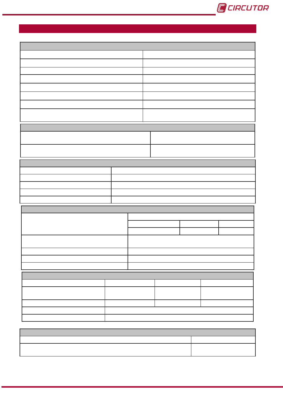
6.- TECHNICAL FEATURES
Electrical features
Usage voltage and nominal frequency
Un / fn, listed on the label
Design voltage
Un + 10%
Nominal power and distribution of steps
Qn and composition, (see label)
Total losses
Typical 1 W/kvar
Residual discharge voltage
75 V after 3 minutes
Overload capacity
1.3 In in all the elements
Auxiliary voltage
Uaux, listed on the label.
Current Transformer
(comes with CVM-MINI-RS485 units)
Secondary winding 5 A, (Transformer In/5 A)
NOTE: Minimum cable section of 2.5 mm
2
.
Protections
Unipolar circuit breaker for single-phase steps
C Curve, Ics: 6 kA / 400 V,
minimum calibre 1.4 In
Three-pole circuit breaker for the three-phase steps
C Curve, Ics: 6 kA / 400 V,
minimum calibre 1.4 In
Capacitor features
Capacity tolerance
± 10%
Insulation level from earth
3 kV /50 Hz
Impulse test
15 kV, ray-type wave 1.2/50 µs
Protections
Internal fuses and over-pressure system
In accordance with Standards
UNE EN 60831
Environmental features
Maximum temperature of capacitors
Category D in accordance with EN 60831-1
Maximum during 1 h.
24 h average
Annual mean
55 ºC
45 ºC
35 ºC
Cabinet ventilation
For outdoor Tamb > 30 ºC forced ventilation should be pro-
vided in the cabinet
Maximum relative humidity
80%
Maximum altitude
2000 m
Protection degree
Marked on the label
Mechanical features
Model
OPTIM HYB1
OPTIM HYB2
OPTIM HYB3
Dimensions (Width x Height x
Depth
)
685 x 970 x 340 mm 800 x 1840 x 640
mm
1000 x 1840 x 640 mm
Weight
71 Kg
183 Kg
336 Kg
Paint
Epoxy type, oven-dried
Standard colours
RAL 7035 Grey; RAL 3005 Maroon
Standards
Power capacitors. Low voltage power factor correction capacitor banks.
UNE-EN 61921:2004
Industrial alternating current networks affected by harmonics. Use of
filters and shunt capacitors.
UNE-EN 61642:2000
31
Instruction Manual
OPTIM HYB Series