Power circuit, Figure 8 – CIRCUTOR OPTIM HYB Series User Manual
Page 18
Advertising
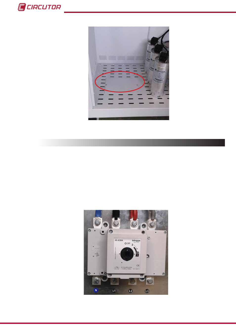
Figure 8: Cable entry point on the OPTIM HYB 2 model.
3.5.-POWER CIRCUIT
Connect input terminals L1, L2, L3 and N (power circuit) to the mains using a cable with a prop-
er section width, in accordance with the LVR, ITC-BT-19.
Generally, the cables of the phases are according to the following colour code: L1 (black), L2
(brown), L3 (grey) and the neutral conductor N (blue).
To determine the size of the phase cables, the maximum nominal current I
max
shown on the unit
label and a transient overload of up to 1.5 times I
max
be taken into account.
The neutral cable
must have the same section as the phase conductor.
Figure 9: Input terminals L1, L2, L3 and N for connecting OPTIM HYB capacitor banks to the mains.
18
OPTIM HYB Series
Instruction Manual
Advertising