Junger Audio d06 - Digital Audio Leveler User Manual
Page 22
3. INSTALLATION
operation manual d06, chapter 3 - Installation - page 8 of 10
Some basic settings can be done by switches and jumpers on the PCB.
These settings are general changes for operation and should be performed by
qualified engineering staff only.
To set any internal jumper or switches it is necessary to open the unit.
Important Note!
DO NOT CHAGE ANY SETTINGS WHILE POWER IS
CONNECTED TO THE UNIT!
Loosen the screws on the top cover and remove. Then you can see all jumper
and switches as shown in the schematic below. After setting of jumper or
switches reassemble the unit in opposite order.
J2 :
RS-232 / RS-422
(format selection)
J3 :
A / B
serial Interface of the DSP controller (A)
or the LAN controller (B)
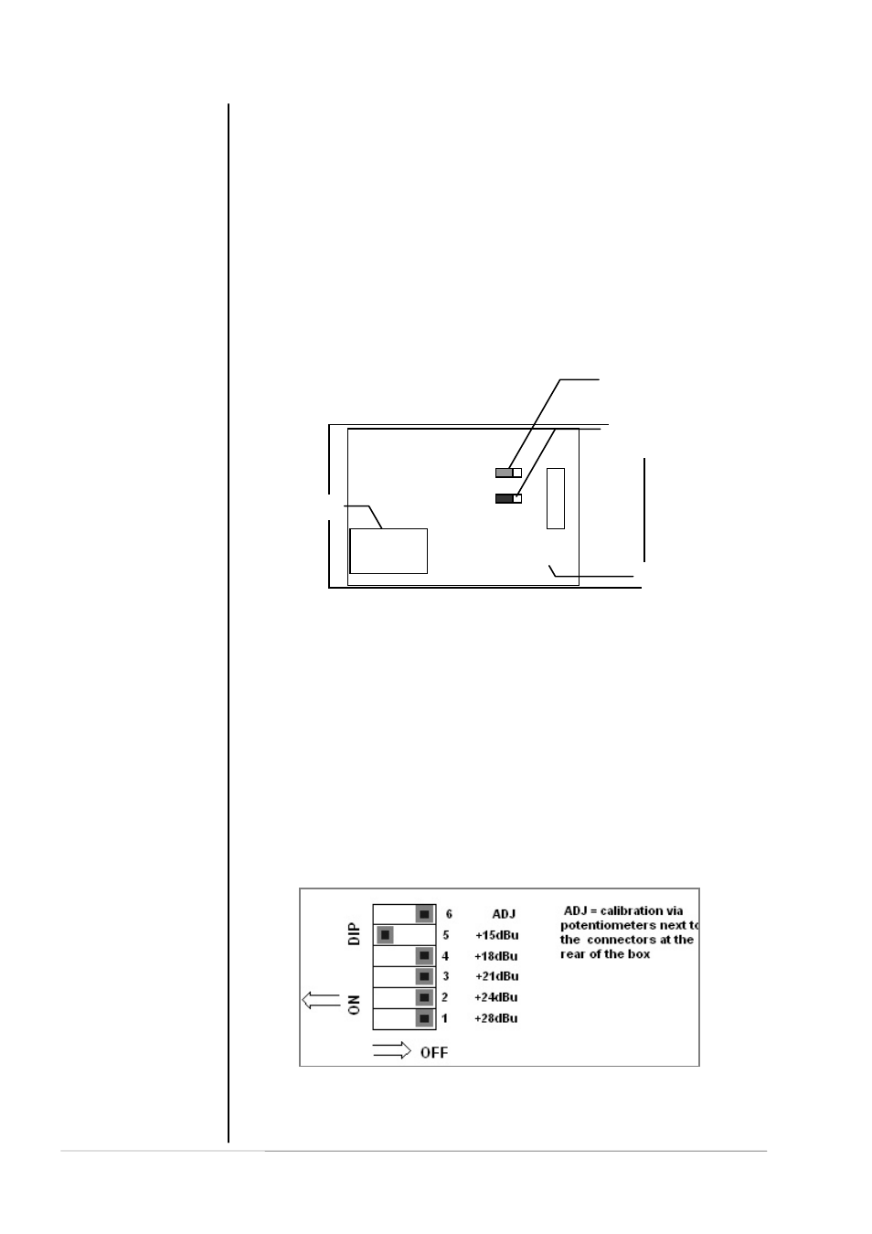
The factory default calibration of the d06 is done in reference to the German
radio broadcast standard, i.e. +15dBu = 0dBFS. If you want to use a different
reference standard (e.g. +24dBu = 0dBFS) you can change the setting via dip
switches on the main board of the d06 :
The DIP switches are located close to the analog input and output hardware
on the PCB.
3.8
Switches and
jumpers for
configuration
3.8.1
Selection of the
serial remote
interface
3.8.2
Calibration of the
analog inputs and
outputs
Main board
J2
232/422
D06/07
J3
A/B
DSP card