Configurations and connecting diagrams, 1 full-range mode – KLING & FREITAG K&F CA 1515-9 - SP User Manual
Page 21
User’s Manual
‘SP’ Models based upon the CA Series
KLING & FREITAG GMBH ©2003 - 2014
Version 7.1, 09.09.2014
Page 21 of 52
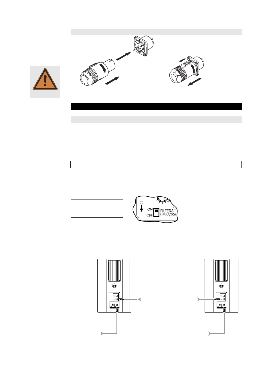
8.2 Connecting the Power Connectors to the Connecting Terminal
2.
1.
3.
1.
2.
Only use the supplied power cable and connect it to a mains outlet with a 16 A fuse.
See instructions in chapter 4 ‘Power Cord’ on page 13.
9. Configurations and Connecting Diagrams
9.1 Operating the Systems without K&F System Controller
The full-range system can be used alone or in conjunction with an SP subwoofer. The
subwoofer has an integrated filter for use in this mode, which limits the bandwidth.
The full-range system is protected against low frequency (subsonic) signals by a high-
pass filter and when used with bass speakers it is phase aligned with the subwoofers by
means of alignment filters.
9.1.1 Full-Range Mode
This mode of operation is ideal for speech and music applications without the need for
a high bass content. Should more bass be needed, the bass level can be increased be-
tween 50 and 80 Hz at the mixing console.
The switch ‘FILTERS’ on
the SP speaker must be
at ‘ON’ in this mode.
If you are operating a mid-range system in a cluster (speakers arranged in close prox-
imity) reduce the frequencies below 300 Hz by 3-4 dB! (The K&F System Controllers
have a special ‘Top Low Cut’ filter function for this purpose.)
INPUT
Channel 2
Channel 1
LINE
AC-MAINS
LINE
AC-MAINS
AC ~ 16 A max.
AC ~ 16 A max.
Warning