Deq-i & ii multi-unit system, Function, Terms used – Oxmoor DEQ-1 User Manual
Page 20: Interconnection scheme, Setting addresses, Page 18
FUNCTION
One of the primary benefits of programmable devices is
that several such devices may be connected together in a
network and controlled from a central location. Up to
250 DEQs (in any combination of DEQ-Is and DEQ-IIs)
may be connected together and controlled by controlling
devices (such as PCs and DEQ-IIs) from many, different
locations. This chapter describes how to connect the
equalizers so that they may all be remotely controlled by
the same controller.
NOTE: PA-422 requires that a devices address be
between 1 and 250. Address 0, 251, 252, 253, 254, and 256
are illegal
.
TERMS USED
COMMUNICATIONS PORT:
The connectors on
the back panel through which serial data
communications occur.
DATAWAY:
The physical wiring that connects the
Communications Ports of two or more equalizers to
form a network.
ADDRESS SELECTOR:
An eight-position dip-
switch which sets the address of the equalizer.
PRESET:
A nonvolatile memory for storing a group
of settings that completely configure an equalizer.
PRESET PORT:
A 15-pin D-connector on the back
panel through which Presets may be selected.
STATUS AREA:
The portion of the LCD display
dedicated to displaying Status information.
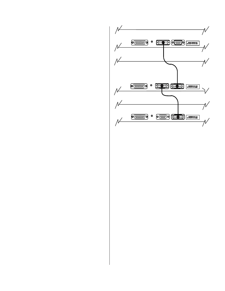
INTERCONNECTION SCHEME
Interconnecting equalizers to permit remote control is
easily accomplished through the Communications Port.
This example system consists of two DEQ-Is and a DEQ-
II which is used as the system controller. Note that the
Communications Port of each DEQ consists of two nine-
pin D-connectors, one marked “PA-422 IN” and the
other “PA-422 OUT.” Notice that the “PA-422 OUT”
connector of one equalizer is connected to the “PA-422
IN” connector of another. For instance, in Figure 6.1, the
“PA-422 OUT” connector of the equalizer at address 1 is
connected to the “PA-422 IN” connector of the equalizer
at address 2. Similarly, the “PA-422 OUT” connector of
the DEQ-II is connected to the “PA-422 IN” connector of
the equalizer at address 3. This interconnection process
is extended when more equalizers (or PCs) are placed in
the system. For example, if you added a new equalizer
you could connect the new equalizer’s “PA-422 OUT”
connector to the address 1 equalizer’s “PA-422 IN”
connector. Or, you could connect the new equalizer’s
“PA-422 IN” connector to the address 3 equalizer’s “PA-
422 OUT” connector. Please note that any mix of DEQ-
Is and DEQ-IIs may be connected together, in any order,
provided the interconnection scheme described above is
followed and there are no more than 250 equalizers in
the network. Also, in this example addresses 1, 2, and 3
were chosen merely for convenience; any three
addresses in the range 1 to 250 could have been used.
The Appendix contains the appropriate wiring
information for the Communications Port, including
connector pin-outs.
SETTING ADDRESSES
NOTE: PA-422 requires that a device's address be
between 1 and 250. Address 0, 251, 252, 253, 254, and 256
are illegal
.
When connecting two or more equalizers together to
form a network, as described in the preceding section, it
is important that each equalizer be given a unique
address. The Address Select dip-switch on the back
panel of both models of the equalizer allows you to give
each equalizer a numerical address ranging in value
from 1 to 250.
Figure 6.1: Interconnection Scheme
DEQ-I & II MULTI-UNIT SYSTEM
Page 18
PA-422 ADDRESS
PA-422 ADDRESS
PA-422 OUTPUT
PA-422 INPUT
PRESET SELECT
PA-422 OUTPUT
PA-422 INPUT
PA-422 OUTPUT
PA-422 INPUT
PA-422 ADDRESS
128
64
32
16
8
4
2
1
ON
PRESET SELECT
128
64
32
16
8
4
2
1
ON
128
64
32
16
8
4
2
1
ON
PRESET SELECT
DEQ-I Set To Address 3
DEQ-II Set To Address 2
DEQ-I Set To Address 1