Deq-i & deq-ii multi-unit system (continued), Using the preset port, Page 19 – Oxmoor DEQ-1 User Manual
Page 21: Pa-422 address
Page 19
DEQ-I & DEQ-II MULTI-UNIT SYSTEM (CONTINUED)
Each equalizer is set to Address 1 at the factory.
NOTE: PA-422 requires that a device's address be
between 1 and 250. Address 0, 251, 252, 253, 254, and 256
are illegal
.
Each of the eight switches in the dip-switch has a
numerical value (see Figure 6.2). These values, reading
from left to right, are 128, 64, 32, 16, 8, 4, 2, and 1. To set
the address of an equalizer, place those switches whose
numerical value sum is equal to the desired address in
the ON position. For example, to set an equalizer to
address 23, the switches should be set as follows.
Additional examples are shown in Figure 6.3:
NOTE: It is very important that each equalizer on the
dataway has a unique address. If more than one equalizer has
the same address, the system will not work properly.
USING THE PRESET PORT
On page 8, we presented one way to select a different
Preset. In that method, the DEQ-II’s control panel was
used, which means that a DEQ-II must be in the system
and that you must be logged on to the system. A way to
switch the equalizer to a different Preset without needing
a DEQ-II (or a PC) is by using the Preset Select port. The
Preset Port, a 15-pin D-connector located on the back panel,
PA-422 ADDRESS
PA-422 ADDRESS
PA-422 OUTPUT
PA-422 INPUT
PRESET SELECT
PA-422 OUTPUT
PA-422 INPUT
PA-422 OUTPUT
PA-422 INPUT
PA-422 ADDRESS
128
64
32
16
8
4
2
1
ON
PRESET SELECT
128
64
32
16
8
4
2
1
ON
128
64
32
16
8
4
2
1
ON
PRESET SELECT
1
2
3
4
5
6
7
8
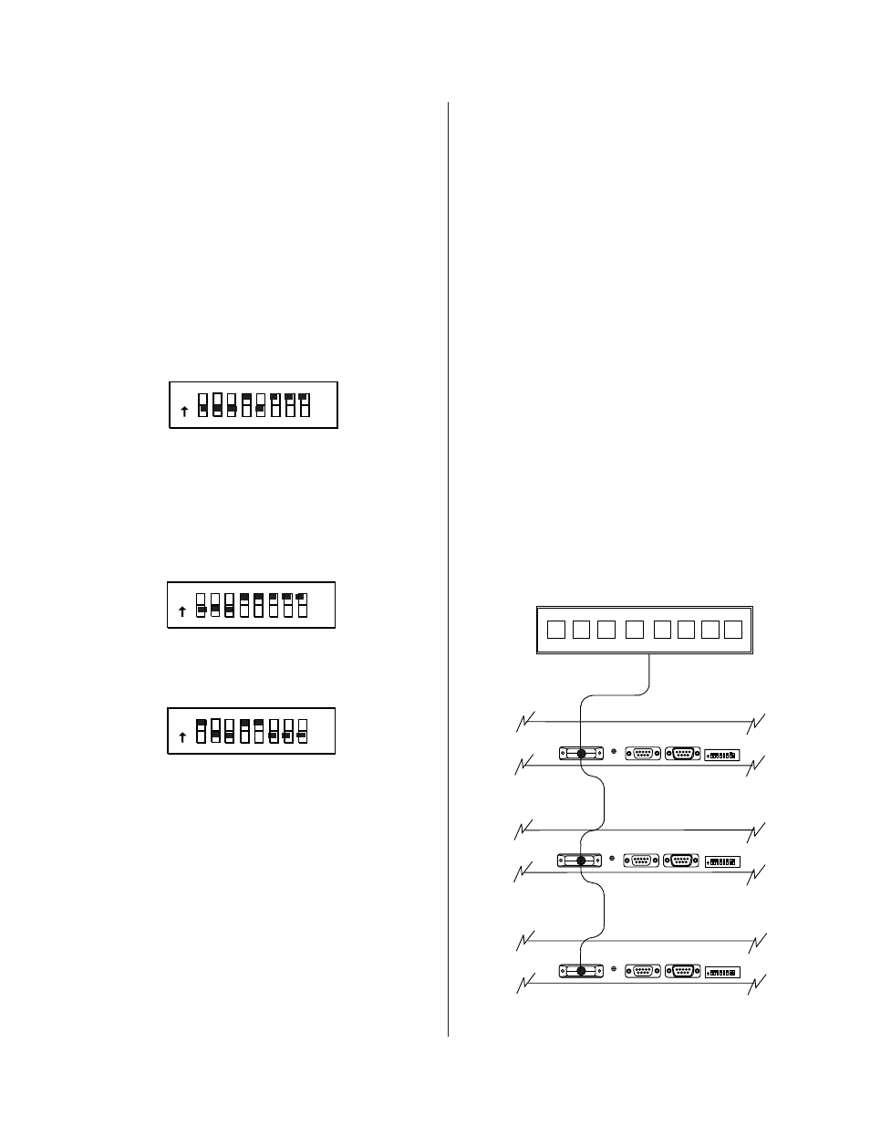
Figure 6.4: Preset Interconnection
will allow you to select a Preset by pushing momentary–
contact push buttons that are connected to the Preset Port.
The Preset Port will also provide a remote indication of
the Preset to which the equalizer is set. The advantage of
this capability is that you may configure your system so
that there are no controlling devices (i.e., PCs or DEQ-IIs)
yet personnel may still call up different Presets that you
have programmed. For example, you may have pro-
grammed one Preset to equalize for speech and another
for music and you may want to be able to switch between
these two Presets. A simple pair of momentary-closure
switches, appropriately connected to the Preset Port,
provides this function. Three "open collector " transistors
provide "tally" outputs at the Preset Select port.
These tallies, property decoded, can be used to provide a
remote indication of the active preset. Appendix F shows
one possible method of decoding tally outputs.
Figure 6.4 shows a typical wiring scheme for the Preset
Port. Here three DEQs are interconnected by their Preset
Ports and to a “remote control panel.” This control panel
is simply a set of switches (and possibly an indicator to
show the active Preset) which allow the selection of Pre-
sets. Although only three equalizers are shown in the il-
lustration, any number of units (up to 250) may be con-
nected together. These may consist of any mix of DEQ-Is
and DEQ-IIs.
Figure 6.2: Address Switch
16 + 4+2+1 =23
128 64 32 16 8 4 2 1
PA-422 ADDRESS
ON
Figure 6.3: Address Switch
128 64 32 16 8 4 2 1
PA-422 ADDRESS
ON
16+8+4+2+1 =31
128 64 32 16 8 4 2 1
PA-422 ADDRESS
ON
128 + 16 + 8 = 152