AGI Security SYS-HC0451 Standalone DVR Quick Start Guide User Manual
Page 9
5
Figure 1-3.
Figure 1-3
You can refer to the following sheet for alarm input and output information.
1,2,3,4,5,
6,7,8,9,10,
11,12,13,14,
15,16
ALARM 1 to ALARM 16. The alarm becomes active in low voltage.
NO1 C1,
NO2 C2,
NO3 C3,
NO4 C4,
NO5 C5 NC5
The first four are four groups of normal open activation output
(on/off button)
NO5 C5 NC5 is a group of NO/NC activation output (on/off button)
CTRL 12V
Control power output. The power output is off when the alarm is
canceled.
+12V
It is rated power output.
Earth cable.
485 A/B
485 communication port. They are used to control devices such as
PTZ. Please parallel connect 120TΩ between A/B cables if there are
too many PTZ decoders.
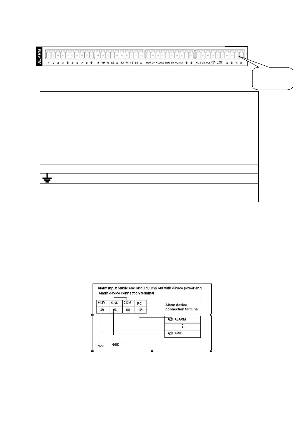
1.9.2 Alarm Input Port
Please refer to the following sheet for more information.
z
Normal open or Normal close type.
z
Please parallel connect COM end and GND end of the alarm detector (Provide external
power to the alarm detector).
z
Use the controllable +12V power to reset the smoke sensor remotely.
z
Please parallel connect the Ground of the DVR and the ground of the alarm detector.
z
Please connect the NC port of the alarm sensor to the DVR alarm input(ALARM)
z
Use the same ground with that of DVR if you use external power to the alarm device.
Figure 1-4
1.9.3 Alarm Output Port
z
Provide external power to external alarm device.
AB cable
connection