3 front panel leds control and status register, Table 8-8, System control register field definition – Artesyn CPCI-6200 Installation and Use (May 2015) User Manual
Page 193: Table 8-9
Memory Maps and Addresses
CPCI-6200 Installation and Use (6806800J66E)
193
8.4.3
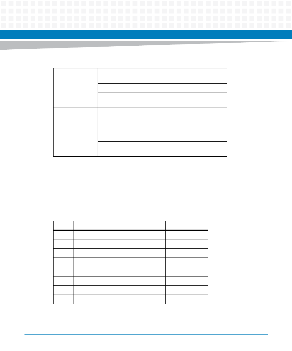
Front Panel LEDs Control and Status Register
This register controls the front panel LEDs. It may be read by the system software to determine
the state of the onboard status indicator LEDs, or written to by system software to make the
corresponding onboard LEDs light up.
Table 8-8 System Control Register Field Definition
BRD_RST
Board Reset. These bits are used to force a hard reset of the
board
101
Hard reset is generated.
xxx
Does not generate hard reset for any other
bit patterns
RSVD
Reserved
EEPROM_WP
EEPROM Write Protect
1
Disable writes to the onboard EEPROM
devices
0
Enable writes to the onboard EEPROM
devices
Table 8-9 Front Panel LED Control/Status Register, 0xF200_0002
Bit
Field
Operation
Reset
7
RSVD
R
0
6
RSVD
R
0
5
RSVD
R
0
4
RSVD
R
0
3
RSVD
R
0
2
RSVD
R
0
1
USR1_LED
R/W
0
0
USR2_LED
R/W
1