Vent requirements, Nstallation, For qualified installers only – Avalon Firestyles DVS Fireplace-1997 to 2000 User Manual
Page 16: Vent terminations, Elbows, Penetration, support parts
P
AGE
16
I
NSTALLATION
(C
ONT
.)
- For Qualified Installers Only!
Vent Requirements
!
Always maintain the required 1" clearance (2" clearance above the vent when an elbow is placed
directly off the top of the fireplace) to combustible materials to prevent a fire hazard. Do not fill air
spaces with insulation.
!
The gas appliance and vent system must be vented directly to the outside of the building, and never
be attached to a chimney serving a separate solid fuel or gas-burning appliance. Each direct vent gas
appliance must use it's own separate vent system.
!
If the fireplace is
installed at an altitude
over 3,000 feet the flame
quality will need to be
carefully evaluated. See
Addendum #1, "Altitude
Considerations", on page
45.
¥
In addition to the
requirements listed to the
right, follow the
requirements provided
with the vent.
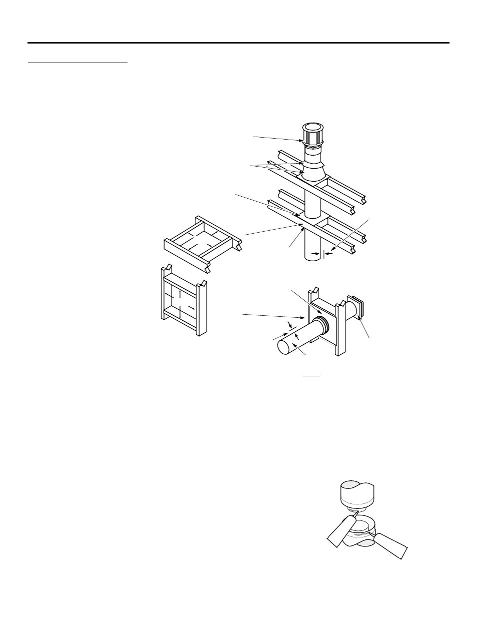
Use a firestop spacer whenever
passing through a ceiling
(Duravent Part #963)
Vertical Termination
(Duravent Part # 991)
Use a roof flashing and storm collar
whenever passing through the roof
(Duravent Part #953 & #943 or #943S)
8-5/8"
(220 mm)
Use a support box
on exposed vent
Vertical Vent
Requirements
Use a firestop whenever
passing through a wall
Horizontal Termination
(Duravent Part #984)
Maintain a minimum 1" clearance from
vent to any combustible (2" above the
vent when an elbow is placed directly
off the top of the fireplace).
Minimum
Framing for
wall thimble
Horizontal Vent
Requirements
Minimum framing
for fire stop
8-5/8"
(220 mm)
Maintain a minimum 1"
(25 mm) clearance from
vent to any combustible
(vent is 6 5/8" (170 mm)
diameter)
6-5/8" Diameter
¥
Use Model GS Direct Vent manufactured by Simpson Dura-Vent
only
. Follow the installation
instructions included with the vent. For the nearest Simpson Dura-Vent supplier, call
(800) 835-4429. Vent part numbers and descriptions are listed below.
Straight Lengths
908B
6" Pipe Length, Black (interior)
907B
9" Pipe Length, Black (interior)
906
12" Pipe Length, Galvanized
906B
12" Pipe Length, Black (interior)
904
24" Pipe Length, Galvanized
904B
24" Pipe Length, Black (interior)
903
36" Pipe Length, Galvanized
903B
36" Pipe Length, Black (interior)
902
48" Pipe Length, Galvanized
902B
48" Pipe Length, Black (interior)
911B
11" to 14 5/8" Pipe, Adjustable, Black (interior)
Vent Terminations
981
Snorkel Termination (36" rise)
(for basement or raised
termination installations)
982
Snorkel Termination (14" rise)
(for basement or raised
termination installations)
984
Horizontal Square Termination
950
Vinyl Siding Stand-off
991
High Wind Vertical
Termination
Elbows
990
90¥ Elbow
990B
90¥ Elbow, Black (interior)
Penetration, Support Parts
942
Wall Thimble
941
Cathedral Ceiling Support Box
943
Flashing, 0/12 to 6/12 Roof Pitch
943S
Flashing, 7/12 to 12/12 Roof Pitch
953
Storm Collar
963
Ceiling Fire-stop
988
Wall Strap
¥
Apply high-temperature silicone to the inner and outer pipe before
assembling the sections (on the male, upper section). This seals the
inner pipe from the outer pipe. Slide the sections together and turn
1/4 turn until the sections lock in place. Install three metal screws
through each joint to lock the outer section in place (see the
instructions included with the vent for further details).
¥
Horizontal sections require a 1/4" rise every 12" of travel
+
Exterior Vent Diameter = 6-5/8", Inner Vent Diameter = 4"
Apply a 1/8" (3 mm)
bead of high-
temperature silicone
to the inner and
outer pipe. The
silicone must seal
the inner pipe from
the outer pipe.
Silicone
Silicone
¥
Horizontal sections require non-combustible support every three feet (e.g.: plumbing tape)