Application coordination – Basler Electric BE1-50/51B-241 User Manual
Page 23
9252000792 Rev D
15
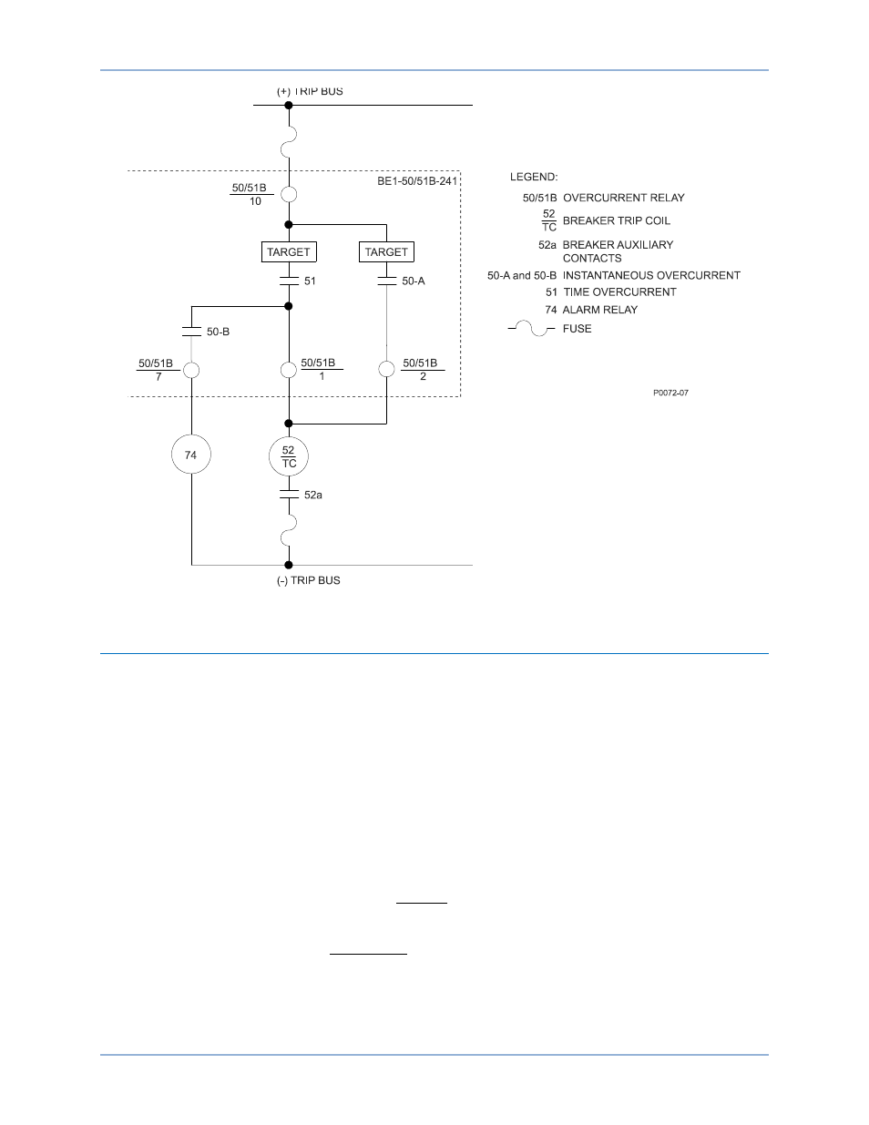
Figure 8. Typical DC Connections
Application Coordination
In a typical application coordination scheme, a BE1-50/51B-241 is used to provide motor protection. An
electromechanical overcurrent relay with extremely inverse timing provides protection for the transformer
and bus. To improve coordination with the electromechanical relay, the BE1-50/51B-241 is configured
with the following settings:
•
Integrating reset enabled (SW3-4 ON)
•
Westinghouse CO/COM type curves selected (SW3-3 OFF)
The feeder reclosing relay is set for two reclose attempts at 3 and 15 seconds after the initial trip. If a
permanent fault occurs (magnitude 10 times pickup), calculate the feeder breaker trip time for each of the
three operations. Refer to the Characteristic Curves chapter for the characteristic curve constants and
definition of the terms used in the following time characteristic curve equations.
From the time characteristic curve equation:
K
BD
C
M
AD
T
N
T
+
+
−
=
028
.
0
)
2
02758
.
0
(
1
10
2
7624
.
7
0938
.
2
+
×
+
−
×
=
= 0.209 seconds
BE1-50/51B-241
Installation