Basler Electric BE1-50/51B-241 User Manual
Page 29
9252000792 Rev D
21
g.
Set INST PICKUP (50-B) (accessed at the top side of the assembly) to F0 (15.0 Aac).
2.
Apply 2 Aac to terminals 8 and 9 to trip the 51 relay output.
3.
Slowly increase the voltage source to provide target current and verify that the Time target operates
at the level of current determined by the Target Operating Current Jumpers.
4.
The Target Operating Current Jumpers are located on the circuit board and identified as J1 and J2.
J1 sets the minimum current range for the 50-A target and J2 sets the minimum current range for the
51 target. A jumper installed across pins 1 and 2 gives a minimum operating current of 0.9 to 2.25 A.
A jumper installed across pins 2 and 3 gives a minimum operating current of 80 to 200 mA.
5.
Remove the target and sensing current and reset the target.
6.
Set TIME PICKUP to 9.0.
7.
Set INST PICKUP (50-A) to 01.
8.
Apply 2 Aac to terminals 8 and 9 to trip the 50-A relay output.
9.
Slowly increase the voltage source to provide target current and verify that the Instantaneous target
operates at the level of current determined by the Target Operating Current Jumpers.
10.
Remove the target and sensing current and reset the target.
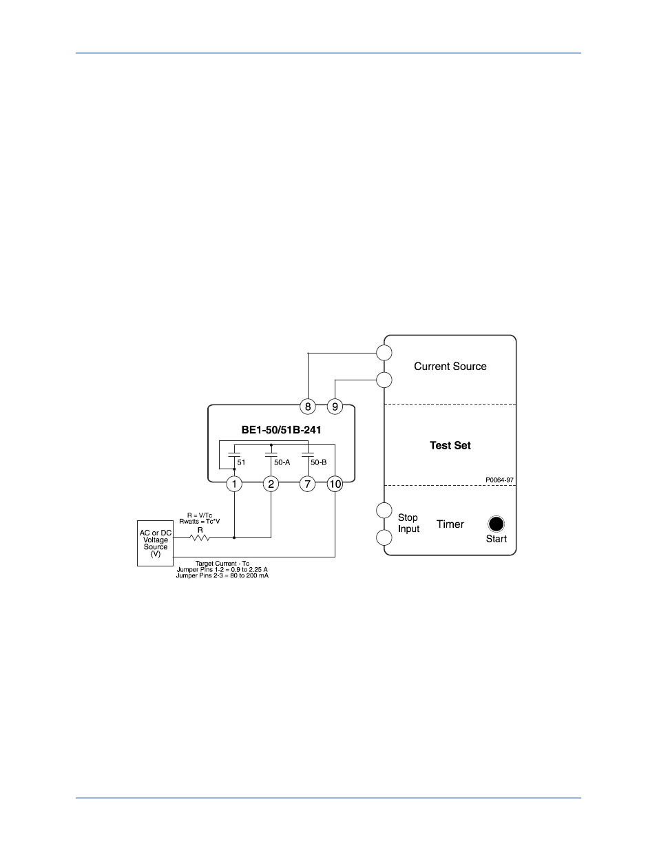
Figure 12. Target Indicator Test Setup
Manual Trip
1.
Configure the relay for manual trip testing:
a.
Connect the test setup as shown in Figure 10.
b.
Set circuit board switch SW3 as follows:
SW3-1 = ON for 50 Hz operation or OFF for 60 Hz operation
SW3-2 = OFF (no additional time delay for the 50-A element)
SW3-3 = ON (Westinghouse CO/COM type characteristic curves)
SW3-4 = ON (integrating reset characteristic)
c.
Set TIME DIAL to 0.0
d.
Set CURVE to S.
e.
Set TIME PICKUP to 1.0.
BE1-50/51B-241
Testing