Basler Electric BE1-50/51B-241 User Manual
Page 27
9252000792 Rev D
19
k.
Set INST PICKUP (50-B) (accessed at the top side of the assembly) to F0 (15.0 Aac).
2.
Apply 4.0 Aac to terminals 8 and 9. After the unit trips, remove the applied current for 29
±0.25
seconds, then reapply the current (4.0 Aac). Note the elapsed time from the reapplication of current to
the second trip. The elapsed time should be 2.08
±0.4 seconds.
Instantaneous Overcurrent A (50-A) Pickup
1.
Connect and configure the relay for 50-A pickup testing:
a.
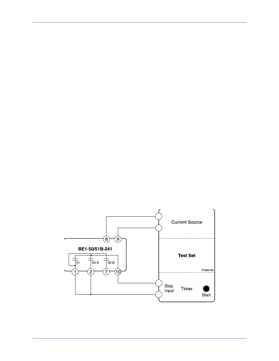
Connect the test setup shown in Figure 10.
b.
Set circuit board switch SW3 as follows:
SW3-1 = ON for 50 Hz operation or OFF for 60 Hz operation
SW3-2 = OFF (no additional time delay for the 50-A element)
SW3-3 = ON (Westinghouse CO/COM type characteristic curves)
SW3-4 = ON (integrating reset characteristic)
c.
Set TIME DIAL to 0.0.
d.
Set CURVE to S.
e.
Set TIME PICKUP to 15.0.
f.
Set INST PICKUP (50-A) to 02.
g.
Set INST PICKUP (50-B) (accessed at the top side of the assembly) to F0 (15.0 Aac).
2.
Apply and slowly increase current to terminals 8 and 9 until the 50-A output contacts close. The
applied current should be between 1.935 and 2.065 Aac.
3.
Decrease the applied current until the 50-A output contacts open.
4.
Set INST PICKUP (50-A) to 08.
5.
Slowly increase the current applied to terminals 8 and 9 until the 50-A output contacts close. The
applied current should be between 7.815 and 8.185 Aac.
6.
Reduce the applied current to zero.
Figure 10. 51 Pickup, Time Dial, Integrating Reset, and 50-A Pickup Test Setup
Instantaneous Overcurrent B (50-B) Pickup
1.
Connect and configure the relay for 50-B pickup testing:
a.
Connect the test setup shown in Figure 11.
BE1-50/51B-241
Testing