Basler Electric BE1-50/51B-230 User Manual
Page 37
9252000894 Rev H
BE1-50/51B-230/-234/-239 Installation
4-5
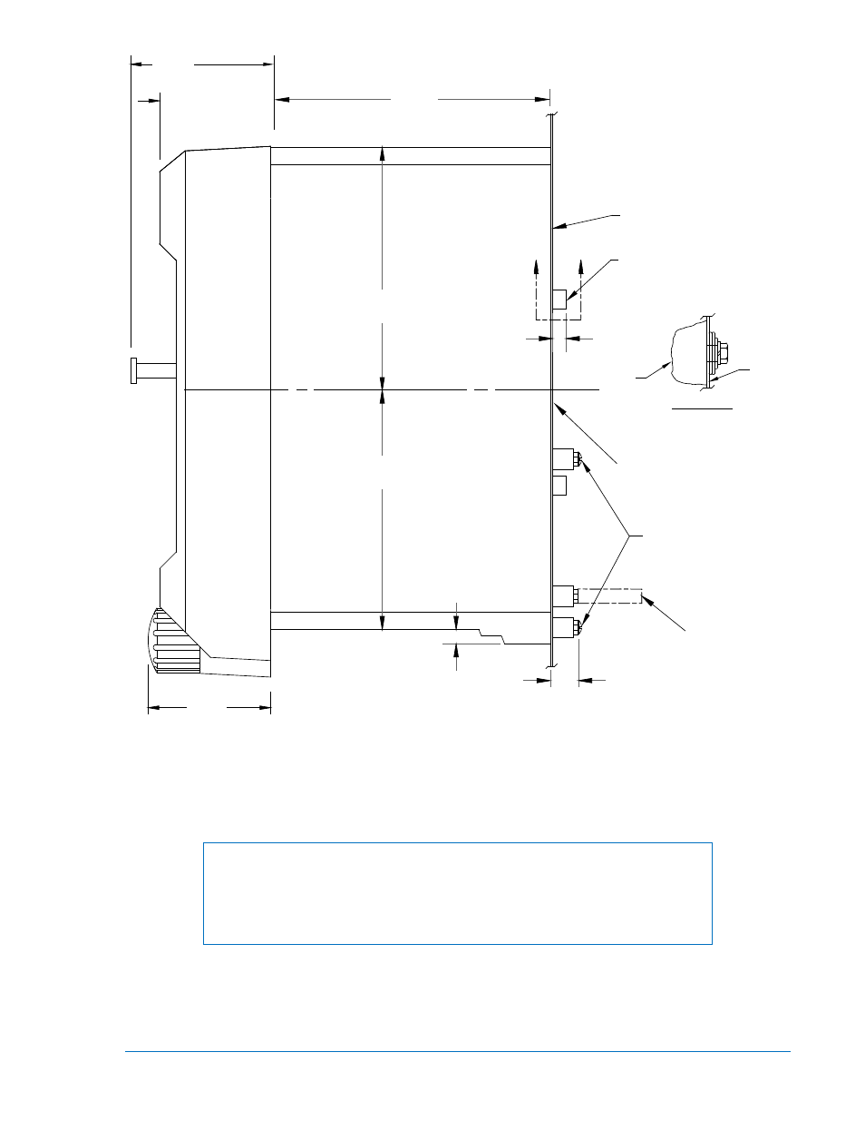
NOTE: PROJECTION MOUNT USES WASHERS OVER THE BOSSES AS SHOWN IN THIS ILLUSTRATION.
Figure 4-4. Outline Dimensions for S1 Case, Projection Mounting
NOTE
Be sure that the relay is hard-wired to earth ground with no smaller than 12
AWG copper wire attached to the ground terminal on the rear of the unit case.
When the relay is configured in a system with other devices, it is
recommended to use a separate lead to the ground bus from each unit..
4.03
4.03
.31
.75
6.19
(19.1)
(7.9)
(102.4)
(102.4)
(157.2)
10-32 SCREWS
MOUNTING PANEL
.25
(6.4)
A
A
5/16-18 STUD
2 PLACES
TERMINAL EXTENSION (TYP.)
FOR DETAILED INSTRUCTIONS.
SEE THE TERMINAL PROJECTION
MOUNTING KIT SUPPLIED.
MOUNTING PANEL
(62.48)
2.195
(55.75)
(49.53)
1.95
2.40
DETAIL A-A
SHOWING THE ADDITION OF WASHERS
OVER THE BOSS TO TIGHTEN THE
RELAY AGAINST THE PANEL.
CASE
PANEL
12-17-99
D2750-25