O figure 29 – Basler Electric BE1-51/27R User Manual
Page 48
42
9137200999 Rev F
(c)
Sensing Input Type U or W (Three-Phase with Neutral Sensing). Refer to Figure 31.
Ensure that the timed output terminals 1 and 10 are connected. Also, verify that either A,
B, or C current sense terminals are connected initially (N terminals will be connected later
in the test).
(d)
Sensing Input Type B or C (Three-Phase Sensing). Refer to Figure 32.
Ensure that the timed output terminals 1 and 10 are connected. Also, verify that either A,
B, or C current sense terminals are connected initially (N terminals will be connected later
in the test). Ensure that the voltage sense terminals and the current sense terminals are
connected to the same phase.
(e)
Sensing Input Type E or F (Three-Phase with Neutral Sensing). Refer to Figure 33.
Ensure that the timed output terminals 1 and 10 are connected. Also, verify that either A,
B, or C current sense terminals are connected initially (N terminals will be connected later
in the test).
(f)
Sensing Input Type Y or Z (Two-Phase with Neutral Sensing). Refer to Figure 34.
Ensure that the timed output terminals 1 and 10 are connected. Also, verify that either A,
B, or C current sense terminals are connected initially (N terminals will be connected later
in the test).
Step 2. Remove the relay front cover.
Step 3. Set the front panel TIME DIAL selector and, if present, the front panel TIME DIAL (NEUTRAL)
selector to 99.
Step 4. Adjust the front panel INST 1 and INST 2 controls, if present, fully clockwise (CW).
Step 5. Adjust the front panel TAP CAL control, and if present, the front panel TAP (NEUTRAL) control
fully CW.
Step 6. Ensure that the relay front panel TARGETS, if present, are reset.
Step 7. Apply 100% of nominal voltage based on the sensing input type for your relay.
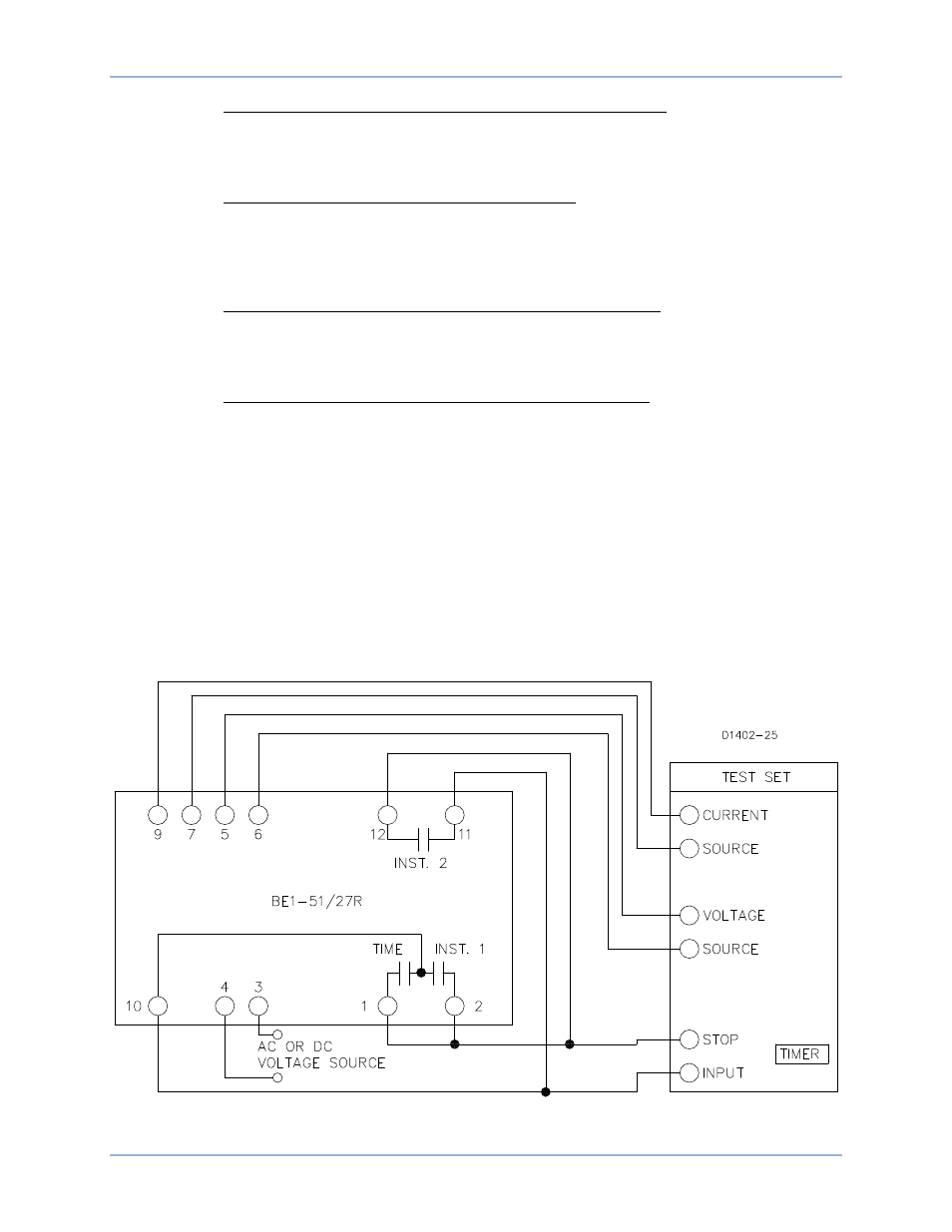
Figure 29. Test Setup for Sensing Input Type M or N (Single-Phase Sensing)
Tests and Adjustments
BE1-51/27R