Ct polarity, Ct polarity -18, Figure 12-19. standard ct polarity -18 – Basler Electric BE1-CDS240 Installation User Manual
Page 20: Figure 12-20. current transformer action -18, Figure 12-21. example of reversed ct polarity -18
CT Polarity
CT polarity is critical to the proper operation of the BE1-CDS240. The sidebar below provides
fundamental information on CT polarity and protective relays.
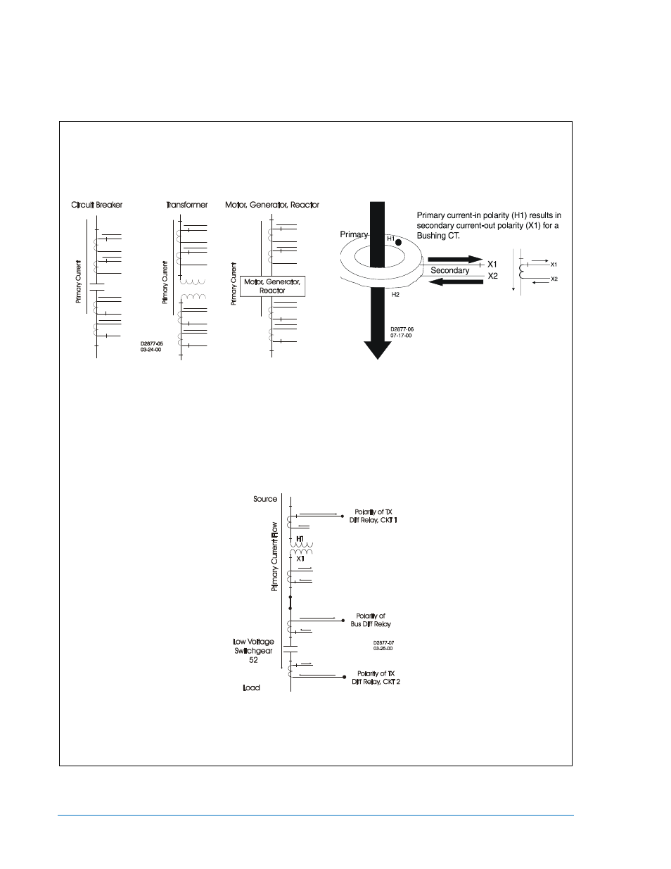
Sidebar: Current Circuit Polarity
By ANSI convention, Current Transformer Polarity will face away from the protected winding of a
transformer, motor, generator, or reactor and away from the contacts in a circuit breaker. Therefore,
primary current flow towards the winding or contacts (direction of protected zone) will result in a
secondary current out X1, in phase with the primary. (See Figures 12-19 and 12-20.)
Figure 12-19. Standard CT Polarity
Figure 12-20. Current Transformer Action
On occasion, however, protection engineers will encounter situations where CT polarity is reversed for
a specific application. That is, non-polarity of the CT secondary will be in phase with the primary
current flow (Figure 12-21). For example, a transformer differential CT from a breaker with a different
polarity convention, such as low voltage switchgear or a bus differential CT taken from the low side of a
transformer.
Figure 12-21. Example of Reversed CT Polarity
Orientation of CT polarity relative to primary current flow establishes the secondary CT terminal that
should be connected to polarity of the protective relay.
12-18
BE1-CDS240 Installation
9365200990 Rev M