Trip coil monitor (tcm) jumpers, Mounting, Trip coil monitor (tcm) jumpers -2 – Basler Electric BE1-CDS240 Installation User Manual
Page 4: Mounting -2
2. Locate the eight jumper terminal blocks (or 12, Option A) that are mounted on the Input/Output
Circuit Board. The Input/Output Circuit Board is the middle board in the assembly and the jumper
terminal blocks are located on the back edge on the component side of the circuit board. Each
terminal block has three pins. With the jumper as installed at the factory, one pin should be visible
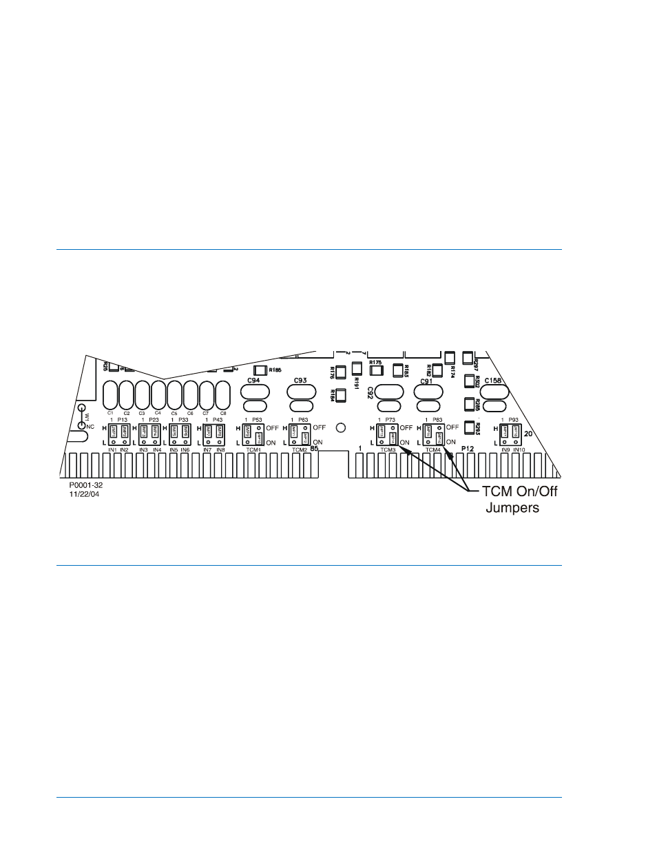
when viewed from the rear of the unit. Figure 12-1 illustrates the location of the jumpers placed in
the high voltage position.
3. To select operation at the lower end of the control voltage range, position the blue jumper on the
two terminals closest to the rear of the circuit board (L). Use care when removing each jumper so
that no components are damaged.
4. When all jumpers are positioned for operation in the desired control voltage range, prepare to
place the drawout assembly back into the case.
5. Align the drawout assembly with the case guides and slide the assembly into the case.
6. Push the latches down until they are parallel with the front panel.
Trip Coil Monitor (TCM) Jumpers
BE1-CDS240 relays have four trip coil monitor circuits for monitoring up to four breaker trip coils. Each
TCM includes a High/Low Input jumper and a TCM On/Off jumper. The High/Low jumper establishes the
operate voltage level of the Input as explained above and the On/Off jumper enables or disables the TCM
logic. The TCMs are associated with Outputs 7, 8, 9, and 10. Relays are shipped with the jumpers in the
TCM ON (active) position. To move the jumper to the off position, follow the procedure outlined under
Contact Sensing Input Jumpers and look for the terminals labeled TCM as shown on Figure 12-1.
Figure 12-1. Contact-Sensing and TCM Jumper Locations
Mounting
Because the unit is of solid-state design, it does not have to be mounted vertically. Any convenient
mounting angle may be chosen. BE1-CDS240 Overcurrent Protection Systems are available in Basler
Electric's MX case design. MX cases are fully drawout with current circuit shorting provisions. MX cases
are available in four configurations: a standard 19-inch rack horizontal mount, a horizontal panel mount,
and two vertical panel mounts (I/O Option "A" and I/O Option "E"). The short vertical panel mount
configuration fits cutout and panel drilling dimensions of Basler Electric M1, GE M1 and M2, and
Westinghouse FT31 and FT32 size cases. The long vertical mounting pane fits cutout and drilling
dimensions of the GE L2 and Westinghouse FT42 cases.
•
Figures 12-2 through 12-4 show the overall dimensions of the case with vertical panel mounting
or horizontal panel mounting, M-size.
•
Figure 12-5 is the panel-drilling diagram for the vertical panel mount or horizontal mount, MX
case.
•
Figures 12-6 through 12-8 show the overall dimensions of the case with the horizontal rack
mounting.
•
Figures 12-9 through 12-11 show the overall dimensions of the case with the vertical panel
mounting, L-size.
12-2
BE1-CDS240 Installation
9365200990 Rev M