Section 12 • installation, General, Contact-sensing input jumpers – Basler Electric BE1-CDS240 Installation User Manual
Page 3: Section 12 • installation -1, General -1, Contact-sensing input jumpers -1, Table 12-1. contact-sensing turn-on voltages -1
SECTION 12 • INSTALLATION
General
BE1-CDS240 Current Differential Systems are delivered with an instruction manual and BESTCOMS™
software in a sturdy carton to prevent shipping damage. Upon receipt of the relay, check the model and
style number against the requisition and packaging list for agreement. If there is evidence of shipping
damage, file a claim with the carrier, and notify the Basler Electric Regional Sales Office, your sales
representative, or a sales representative at Basler Electric, Highland, Illinois.
If the BE1-CDS240 is not installed immediately, store it in the original shipping package in a moisture and
dust free environment.
Contact-Sensing Input Jumpers
NOTE
The BE1-CDS240 relays with mid- or high-range power supplies are delivered
with the jumpers in the H (HIGH) position. Read the following paragraphs
before placing the relay in service.
BE1-CDS240 relays have eight or twelve contact-sensing inputs, depending on style number, to initiate
relay actions. An external wetting voltage is required for the contact-sensing inputs. The nominal voltage
level of the external dc source must comply with the dc power supply input voltage ranges listed in
Section 1, General Information, Specifications. To enhance user flexibility, the BE1-CDS240 uses wide
range ac/dc power supplies that cover several common control voltages. The contact sensing input
circuits are designed to respond to voltages at the lower end of the control voltage range while not
overheating at the high end of the range.
Energizing levels for the contact-sensing inputs are jumper selectable for a minimum of approximately 5
Vdc for 24 Vdc nominal sensing voltage, 26 Vdc for 48 Vdc nominal sensing voltages, or 69 Vdc for 125
Vdc nominal sensing voltages. See Table 12-1 for the contact-sensing turn-on voltages.
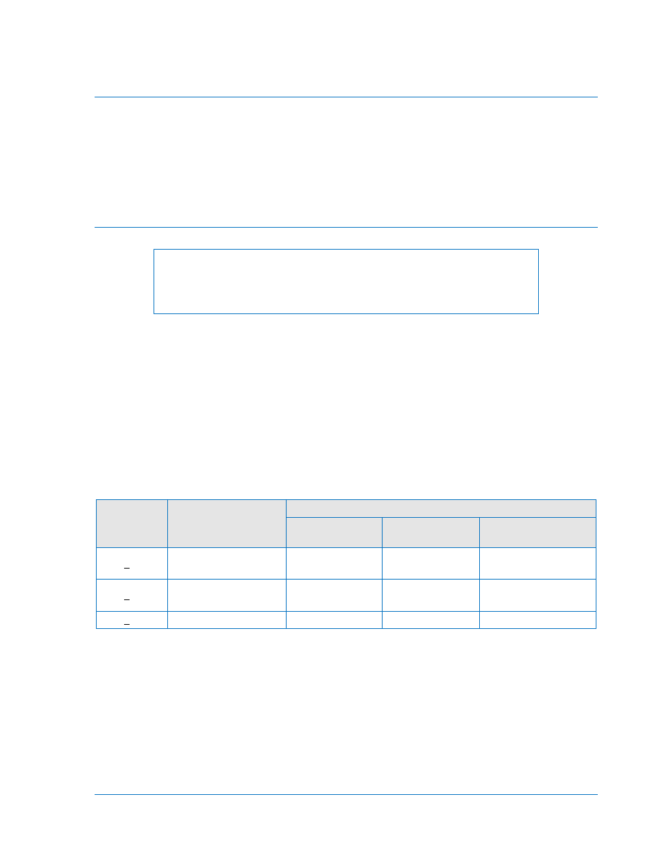
Table 12-1. Contact-Sensing Turn-On Voltages
Style
Option
Nominal Input
Voltage
Contact-Sensing Turn-On Voltage *
Jumper (L)
(Low Position)
Jumper (H)
(High Position)
Jumper Not
Installed
xxxx1xxxxxx 48 Vdc or 125 Vac/dc
26 to 38 Vdc
69 to 100 Vdc
56 to 97 Vac
n/a
xxxx2xxxxxx
125/250 Vac/dc
69 to 100 Vdc
56 to 97 Vac
138 to 200 Vdc
112 to 194 Vac
n/a
xxxx3xxxxxx
24 Vdc
n/a
n/a
Approx. 5 Vdc
*
AC voltage ranges are calculated using the default recognition time (4 ms) and debounce time (16 ms).
Each BE1-CDS240 with a mid- or high-range power supply is delivered with the contact-sensing jumpers
installed (H position) for operation in the higher end of the control voltage range. If the contact-sensing
inputs are to be operated at the lower end of the control voltage range, the jumpers must be changed to L
position.
The following paragraphs describe how to locate and remove/change the contact sensing input jumpers.
1. Remove the drawout assembly by pulling the two latches outward and sliding the assembly out of
the case. Observe all electrostatic discharge (ESD) precautions when handling the drawout
assembly.
9365200990 Rev M
BE1-CDS240 Installation
12-1