Rs-485 connectors, Rs-485 connectors -26, Table 12-3. rs-485 pinouts (com 2) -26 – Basler Electric BE1-CDS240 Installation User Manual
Page 28
Advertising
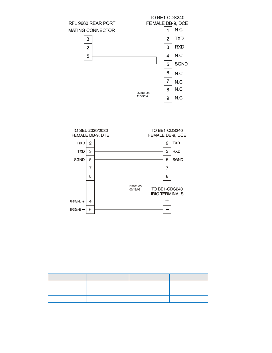
Figure 12-30. RFL9660 Protective Relay Switch to BE1-CDS240 Cable
Figure 12-31. SEL 2020/2030 to BE1-CDS240 Relay
RS-485 Connectors
RS-485 connections are made at a three-position terminal block connector which mates with a standard
communication cable. A twisted pair cable is recommended. Connector pin numbers, functions, names,
and signal directions are shown in Table 12-3. An RS-485 connection diagram is provided in Figure
Table 12-3. RS-485 Pinouts (COM 2)
Terminal
Function
Name
Direction
B8 (A)
Send/Receive A
(SDA/RDA)
In/Out
B7 (B)
Send/Receive B
(SDB/RDB)
In/Out
B6 (C)
Signal Ground
(GND)
N/A
12-26
BE1-CDS240 Installation
9365200990 Rev M
Advertising