2 • controls and indicators, Introduction, Section 2 – Basler Electric BE1-47N User Manual
Page 15: Controls and indicators -1
9170400990 Rev J
BE1-47N Controls and Indicators
2-1
SECTION 2 • CONTROLS AND INDICATORS
Introduction
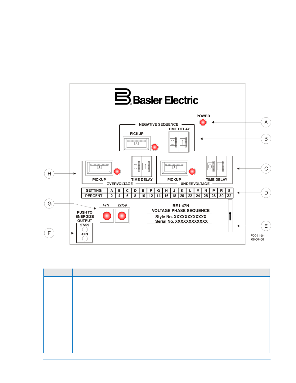
All BE1-47N controls and indicators are located on the front panel. The controls and indicators are shown
in Figure 2-1 and described in Table 2-1. Figure 2-1 illustrates a relay with the maximum number of
controls and indicators. Your relay may not have all of the controls and indicators shown and described
here.
Figure 2-1. BE1-47N Controls and Indicators
Table 2-1. Control and Indicator Descriptions
Locator
Description
A
Power Indicator. This red LED lights when operating power is applied to the relay.
B
Negative Sequence Voltage Controls and Indicator. These elements consist of a pickup
thumbwheel switch, a time delay thumbwheel switch, and a pickup indicator.
The 16-position pickup switch adjusts the negative sequence voltage pickup setpoint.
Switch positions A through S correspond to setpoints ranging from 2 to 32% of the
nominal voltage, in 2% increments. The front panel setting chart (locator D) lists the
setpoint for each switch position.
Relays with definite or inverse timing have a time delay switch that sets the duration of
timing for negative sequence voltage protection. Instantaneous timing is not user-
adjustable, so relays with instantaneous timing do not have a time delay switch.
The red pickup LED lights when the level of negative sequence voltage exceeds the
setting of the negative sequence voltage pickup switch.