Connections, Control circuit – Basler Electric BE1-47N User Manual
Page 33
9170400990 Rev J
BE1-47N Installation
4-9
Connections
Be sure to check the model and style number of a relay before connecting and energizing the relay.
Incorrect wiring may result in damage to the relay. Except where noted, connections should be made with
wire no smaller than 14 AWG.
Typical external connections are shown in Figures 4-8 and 4-9. Typical internal connections are shown in
Figure 4-10.
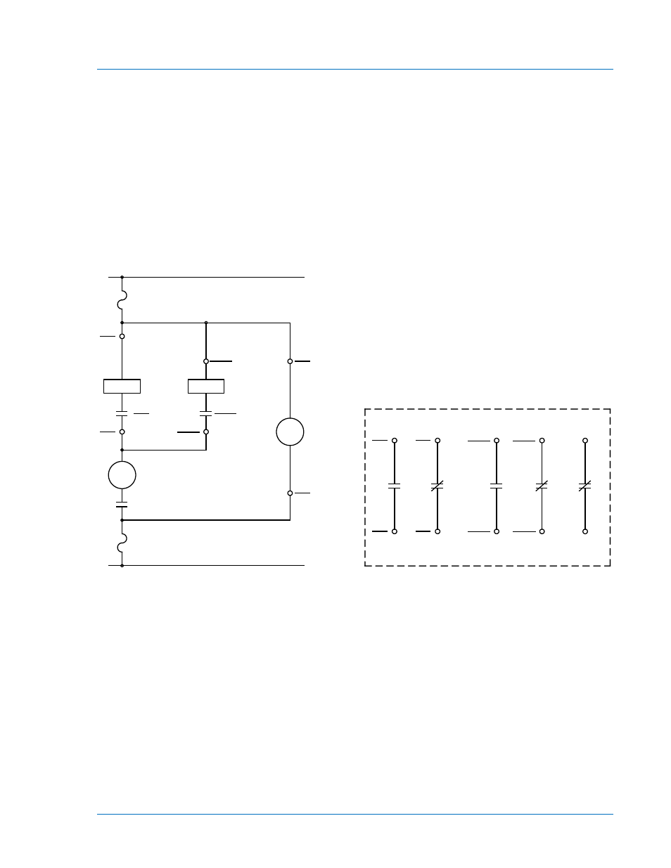
Figure 4-8. Control Circuit Diagram
47N
10
52a
1
47N
47N
T
52
TC
TARGET
47N
3
4
47N
27/59
2
TARGET
27/59
T
27/59
5
POWER
-DC
+DC
CONTROL CIRCUIT
LEGEND:
47N
27/59
52a
52 TC
T
VOLTAGE PHASE SEQUENCE
UNDER/OVERVOLTAGE
BREAKER AUXILIARY CONTACTS
BREAKER TRIP COIL
TIMED
POWER
SUPPLY
STATUS
47N
12
47N
11
11
47N
12
47N
OR
OR
27/59
20
27/59
19
19
27/59
20
27/59
(47N)
(27/59)
16
17
AUXILIARY CONTACTS
P0066-91