Thumbwheels, Instantaneous trip enable (optional), Microprocessor – Basler Electric BE1-79M User Manual
Page 28: Program monitor, Power loss detector, Thumbwheels -4, Instantaneous trip enable (optional) -4, Microprocessor -4, Program monitor -4, Power loss detector -4
3-4
BE1-79M Functional Description
9170100990 Rev N
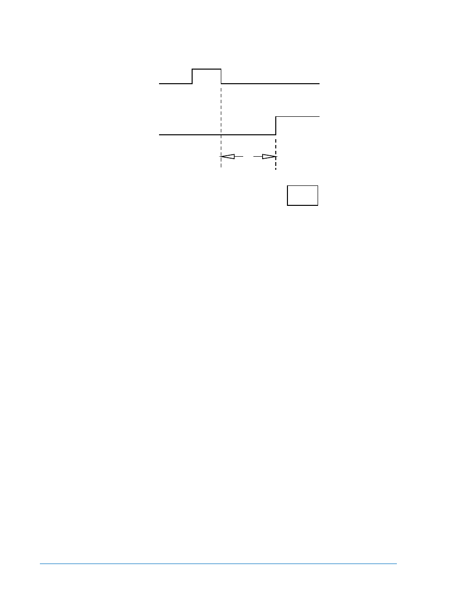
RI, PI
52b
RECOGNITION
DROPOUT TIME
6-17-91
D806-008
Switch S23, on the edge of the contact sensing board, is accessible by removing the drawout cradle from
the case. When S23 is changed to select different functions, the relay must be powered down and power
reapplied to enable selected functions.
Figure 3-3. Recognition Dropout Timing
Thumbwheels
Front panel thumbwheel switches allow the user to program various time settings and limit reclosure
attempts. The switches select individual diodes, producing binary coded decimal words, which are read
by the microprocessor.
Instantaneous Trip Enable (Optional)
Five front panel toggle switches allow the user to select ENABLE or BLOCK instantaneous tripping of the
circuit breaker. Instantaneous tripping may be enabled or disabled for any single trip or combination of
trips. The microprocessor interrogates the individual switches at appropriate times to determine the
desired state of the instantaneous trip enable output contacts. When LOCKOUT or RESET occurs and
normally open ITE, the instantaneous trip enable output contacts are closed while the breaker is closed if
instantaneous trip enable switch 1 is in the enable position.
Microprocessor
The BE1-79M uses an 8-bit, low power, CMOS microprocessor which performs all timing and decision-
making functions.
Program Monitor
Operation of the microprocessor is monitored by the program monitor. In normal operation, the micropro-
cessor outputs pulses at regular intervals. If these pulses are disrupted, the program monitor stops
microprocessor operation and forces the output buffers to high impedance. This causes all output con-
tacts to assume their normal states and lights the RELAY FAIL LED. If this situation is the result of
something other than hardware failure, it may be remedied by momentarily interrupting operating power.
Power Loss Detector
The power loss detector circuit compares the output of the power supply to a reference voltage. If the
power supply output falls below the reference voltage, the power loss detector circuit sends an interrupt
signal to the microprocessor. Upon receipt of this signal, the microprocessor stores status data in the non-
volatile reclose sequence memory. This data indicates the progression of a reclosing sequence or state of
the Multiple Shot Reclosing Relay at the time power was lost. At this point, the relay fail contacts close
and all further functions of the relay cease until input power is removed and restored. When power is
restored, the microprocessor uses this data, if logic switch S23 memory save function is enabled and the
power loss occurred during a reclosing sequence, to resume operation from the point of power loss. The
relay compensates for any change of state of the breaker which may have occurred during power off.
However, the remaining least significant digits of the maximum cycle time, reclose delay time, and the
remaining reclose fail time are not stored. If the two most significant digits of the remaining maximum