Test plug adapter, Function, Test plug adapter -3 – Basler Electric BE1-79M User Manual
Page 69: Function -3, Figure 7-1. external connections, Reclosing
9170100990 Rev N
BE1-79M Difference Data
7-3
NOTE:
1.
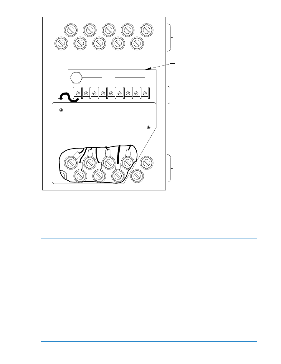
When projection mounting has been selected, the power module must be removed prior to installation
and then attached to the rear of the mounting panel after the relay has been installed. External
contact sensing inputs are then wired to the power module.
Figure 7-1. External Connections
Test Plug Adapter
Function
Relays revision D and previous have voltage-dropping resistors mounted externally on the back side of
the case. These resistors are part of the internal circuitry, despite their external location. When using test
plug, (Basler part number 10095), with these relays, compensating resistors must be added. For ease of
use, Basler Electric has manufactured test plug adapters with internal compensating resistors. Table 7-1
provides the appropriate test plug adapter part number for each power supply type. The test plug adapter
is shown attached to the test plug in Figure 7-3. The adapter should be attached to the test plug before it
is inserted into the relay.
If the correct adapter is not available, a test setup may be improvised by inserting the proper resistors in
series with certain test plug terminals as shown in Figure 7-4. Notice that supplementary terminals (not
supplied by Basler Electric) have been added for convenience in making the connections.
19
20
17
18
15
16
13
14
11
12
9
10
8
7
6
5
4
3
2
1
SOLID-STATE PROTECTIVE RELAY
Reclosing
TB1
G
10
8
9
6
7
5
4
3
#1 AND #2 OUTPUT
CONTACT EXTERNAL
CONNECTIONS
AND POWER SUPPLY
FOR CONTACT INPUTS
EXTERNAL CONNECTIONS
EXTERNAL
OUTPUT CONTACT
CONNECTIONS
POWER MODULE (NOTE 1)
11-16-95
D806-011