Connections, Connections -9, Figure 4-8. sensing input connections – Basler Electric BE1-79M User Manual
Page 49
9170100990 Rev N
BE1-79M Installation
4-9
Connections
Incorrect wiring may result in damage to the relay. Be sure to check model and style number against the
options listed in the Style Number Identification Chart before connecting and energizing a particular relay.
NOTE
Be sure the relay case is hard-wired to earth ground with no smaller than 12
AWG copper wire attached to the ground terminal on the rear of the relay
case. When the relay is configured in a system with other protective devices, it
is recommended to use a separate lead to the ground bus from each relay.
Connections should be made with minimum wire size of 14 AWG except as noted for the ground wire.
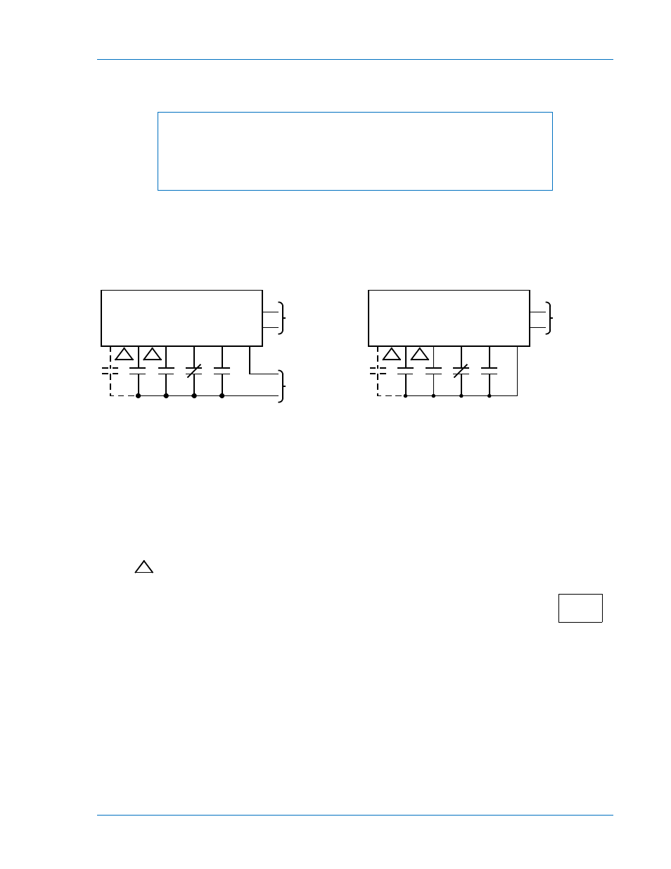
Typical external connections are shown in Figures 4-8 through 4-10. Internal connections are shown in
Figure 4-11.
Figure 4-8. Sensing Input Connections
BE1-79M
4
3
OPERATING
POWER
8
5
7
6
10
9
PI
RI
DTL
52b
IRB
-
+
SENSING
POWER
NON-ISOLATED SENSING
1
1
1
1
ISOLATED SENSING
IRB
52b
DTL
RI
PI
9
10
6
7
5
8
POWER
3
4
BE1-79M
OPERATING
LEGEND:
RI RECLOSE INITIATE SENSING INPUT CONTACTS
DTL DRIVE-TO-LOCKOUT SENSING INPUT CONTACTS
52b CIRCUIT BREAKER SENSING INPUT CONTACTS
IRB INSTANTANEOUS RECLOSE BYPASS SENSING INPUT CONTACTS
PI PILOT INITIATE SENSING INPUT CONTACTS (OPTIONAL)
RST INH RESET INHIBIT SENSING INPYT CONTACTS (OPTIONAL)
REC WAIT RECLOSE WAIT SENSING INPUT CONTACTS (OPTIONAL)
RP RECLOSE PERMISSIVE SENSING INPUT CONTACTS (OPTIONAL)
IF OPTION 1 IS 1
PI IS REPLACED WITH RST INH.
IF OPTION 1 IS 2
RI IS REPLACED WITH REC WAIT.
IF OPTION 1 IS 4
RI IS REPLACED BY RP.
1
11-14-91
D729-006
BE1-79M