Controls and indicators – Basler Electric RDP-110 User Manual
Page 13
9318100990 Rev H
5
Controls and Indicators
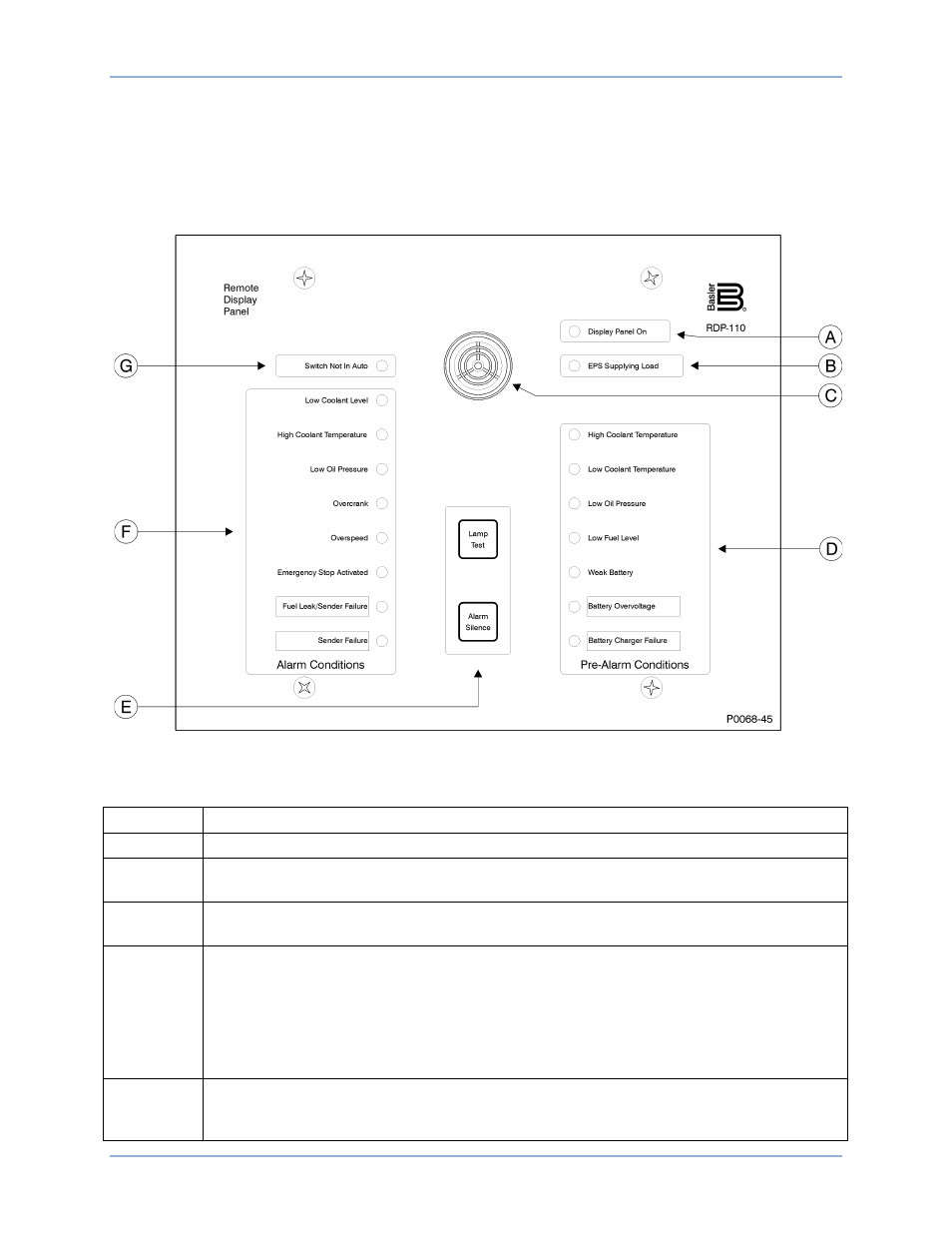
RDP-110 controls and indicators consist of pushbuttons, LED lamps, and an audible alarm (horn). These
front panel elements are illustrated in Figure 2. Lettered locators in Figure 2 correspond to the lettered
descriptions of Table 2.
Figure 2. Controls and Indicators
Table 2. Control and Indicator Descriptions
Locator
Description
A
Green Display Panel On LED lights when control power is applied to the RDP-110.
B
Green EPS Supplying Load LED lights when the genset is supplying more than 2% of
rated load.
C
The horn sounds when an alarm or pre-alarm exists or the connected DGC is not operating
in Auto mode. The horn is silenced by pressing the Alarm Silence pushbutton (locator E).
D
The amber Pre-Alarm LEDs light when the corresponding pre-alarm setting is exceeded.
Conditions annunciated by the pre-alarm LEDs include high coolant temperature, low
coolant temperature, low oil pressure, low fuel level, weak battery, battery overvoltage, and
battery charger failure. When the RDP-110 is used with a DGC-2020, the bottom two LEDs
(Battery Overvoltage and Battery Charger Failure) can be reprogrammed to indicate other
pre-alarm conditions. See Programmable Alarm and Pre-Alarm Configuration for
information about configuring the two programmable pre-alarm indicators.
E
RDP-110 controls consist of two pushbuttons. The Alarm Silence pushbutton silences the
horn (locator C). The Lamp Test pushbutton can be used to verify operation of all RDP-110
LEDs and the horn.
RDP-110
1BControls and Indicators