Installation, Mounting, Connections – Basler Electric RDP-110 User Manual
Page 19
9318100990 Rev H
11
Installation
A NEMA 1 enclosure makes the RDP-110 resistant to moisture and dust infiltration. Its metal construction
improves immunity to electromagnetic interference. Conduit knockouts on the case enable the RDP-110
to be used as a “pass-through” or junction box for other site wiring. Two available mounting configurations
provide the option of semi-flush mounting or surface (projection) mounting.
If the RDP-110 will not be installed immediately, store it in the original shipping package in a moisture-
and dust-free environment.
Mounting
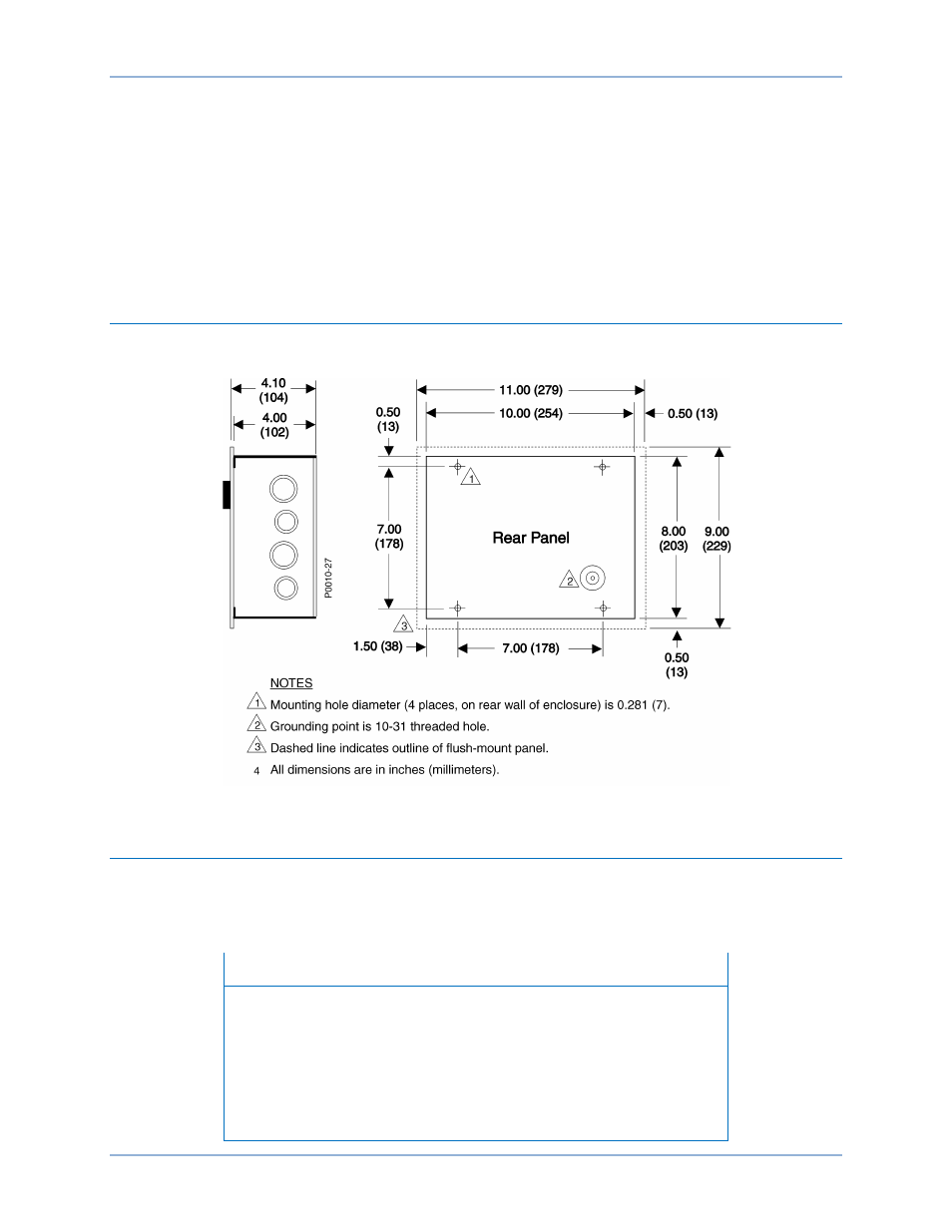
RDP-110 mounting dimensions are illustrated in Figure 5.
Figure 5. RDP-110 Mounting Dimensions
Connections
Display panel connections are made with two plug-in connectors that mate with headers on the lower
edge of the RDP-110 circuit board. Keyed connectors prevent improper connections. These circuit board
connections, illustrated in Figure 6, are accessed by removing the front panel from the conduit box.
Note
Ensure that the RDP-110 is hard-wired to earth ground with no smaller
than 16 AWG (1.5 mm
2
) copper wire attached to the circuit board
CHASSIS terminal. An additional ground connection is provided on the
conduit box.
DC control power applied to the 12/24 (+) and DC COM (–) terminals
must be of the correct polarity. Incorrect dc control power polarity will
prevent the RDP-110 from functioning.
RDP-110
4BInstallation