Functional description, Inputs, Control power – Basler Electric RDP-110 User Manual
Page 17: Communication interface, Pushbuttons
9318100990 Rev H
9
Functional Description
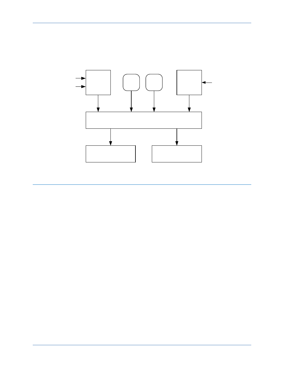
The RDP-110 uses microprocessor-based technology to provide remote annunciation of engine and
generator parameters. RDP-110 function blocks are illustrated in Figure 4 and described in the following
paragraphs.
Figure 4. RDP-110 Function Blocks
Inputs
RDP-110 inputs consist of control power inputs, a communication interface, and pushbuttons. Control
power and communication connections are made on the circuit board attached to the front panel.
Control Power
Redundant, isolated control power inputs enable continued RDP-110 operation if one power input is lost.
The dc control power input accepts nominal battery voltage of 12 Vdc or 24 Vdc. The acceptable range of
dc control power is 8 to 32 Vdc.
The ac control power input is rated for a nominal voltage of 100 Vac or 120 Vac at 50 Hz or 60 Hz. The
acceptable range of ac control power is 80 to144 Vac.
Each control power input is applied to an internal switching power supply that provides filtered 5 Vdc
operating power for the RDP-110 circuitry.
Communication Interface
RDP-110 annunciation commands are received from the DGC over an RS-485 serial communication bus.
Received communication inputs are converted to signals suitable for use by the RDP-110
microprocessor.
Pushbuttons
Two front-panel pushbuttons accept local inputs: Lamp Test and Alarm Silence.
LED and horn operation can be verified by pressing the Lamp Test pushbutton.
An audible alarm is reset by pressing the Alarm Silence pushbutton. Once reset, the horn is reactivated
only the occurrence of another, separate pre-alarm or alarm condition.
Microprocessor
Power
Supply
RS-485
Interface
Lamp
Test
Alarm
Silence
LED Indicators
Audible Alarm
12/24 Vdc
100/120 Vac
From DGC
D
2
8
2
9
-1
9
RDP-110
4BFunctional Description