BUG-O Systems CWP-18 User Manual
Page 8
8
SETUP, CONT’D.
WIRE SPEED AND VOLTAGE ADJUSTMENT
The wire speed control on the front of the CWP-1810
Wire Feed Control Box has a dial that is calibrated directly
in inches per minute. Voltage can be controlled on the
power source or with the NA-3 controller. To use the
NA-3 controls, set the power source voltage control to
REMOTE.
MACHINE CONTROLS
Operational parameters can be set using the two control
boxes. Please refer to the section in this manual entitled
CBP-1550 Rotational Control (page 10) for descriptions
of the various speed and directional capabilities. For the
NA-3 Wire Feeder Control, refer to the supplied NA-3
Semiautomatic Wire Feeder Manual from Lincoln Electric.
INSTALLATION
Use a 3-Jaw Chuck to mount and center the CWP-18 on
nozzles with or without flanges, as seen in Figure1. See
page 34 for a listing of available 3-Jaw Chucks.
WHEEL ADJUSTMENT
The CWP-18 Motorized Racking System CBP-1840 and the Horizontal
Racker CWO-1690-MH are equipped with adjustable wheels. Always
check these components for proper wheel adjustment before using
the machine. The wheels need adjustment if you can cock or wiggle
the components out of alignment. The wheels should be snug, but not
prohibit movement along the path of travel. The wheels with the hex
stand offs are adjustable. To adjust the wheels, loosen the hex bolt
(A) until the adjustable bushing (B) can be rotated. Correct the wheel
alignment by rotating the adjustable bushing
(B). Once adjusted, hold
the adjustable bushing
(B) while tightening the hex bolt (A). Recheck
alignment.
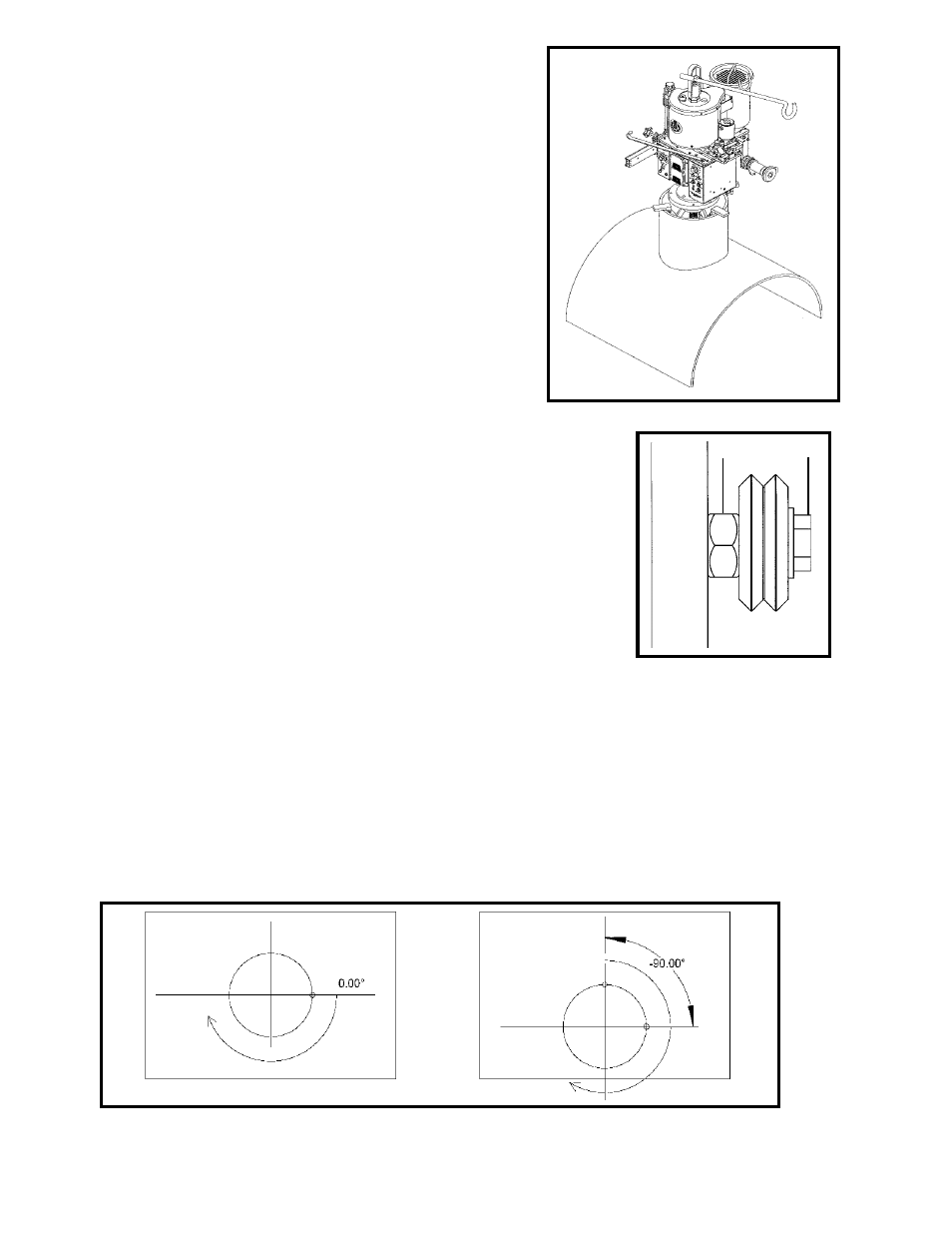
WELD STARTING POSITION
Proper positioning of the electrode is crucial to a successful weld. The CWP-18 rotates in a
clockwise direction. Depending on the job, whether on-center or hillside, or the process, the
optimum starting point of the weld may vary. The desired starting position should be entered at
setup as an angle to the pipe axis direction, as shown in Figure 3.
The default start position (start angle = 0.00°) is shown as A and B in Figure 3. For an on-
center joint, this would be the topmost point. For a hillside joint, -90.00° is the topmost point (C
in Figure 3) and 90.00° is the lowest point.
During setup, enter the Start Angle in hundredths of degrees: 4500 is 45.00°. The machine
makes one revolution from the start point for each pass. Overlap is only added to the last pass.
Figure 3: Weld Start Position for On-center (left) and Offset or Hillside (right) nozzles.
A
C
B
A
B
Figure 1: Installation with 3-Jaw Chuck
Figure 2: Adjustable Wheel