Cwp-1810 na-3 wire feeder controls – BUG-O Systems CWP-18 User Manual
Page 9
9
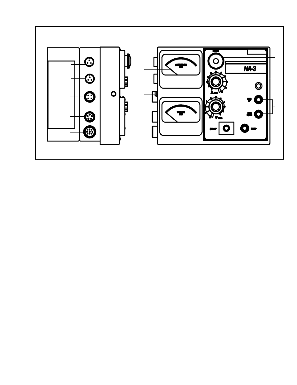
CN1
CN0
A
G
F
D
E
C
B
CN2
CN3
CN4
Figure 4: Side and Front views of Lincoln NA-3 Control Box. (Not to Scale.)
CONTROLS (A-G)
A. Ammeter - Indicates current only while welding.
B. Circuit Breaker - Protects the circuit from severe wire feed motor overload and short
circuits. Press to reset. Locate and correct the cause for overload.
C. Voltmeter (Standard) - Indicated welding voltage only while welding. Also indicates OCV
below 60 volts.
D. Current Control - Adjusts wire feed speed to control welding current.
E. Inch Up & Inch Down - Press to inch electrode at the speed set by “Inch Speed” control
on inner panel.
F. Voltage Control - Adjust arc volts by controlling power source output voltage.
G. Control Power Switch - Turns input control power “On” and “Off”. Also used as an
emergency “Off” in case of malfunction.
CABLE CONNECTIONS (CN0 - CN4)
CN0 Connects to Contactor Box via CWP-1816
CN1 (Unused)
CN2 Connects to Rotation Control Box via Power Cable
CN3 Connects to Wire Feeder Motor (Cable is integral to Wire Feeder Motor)
CN4 Connects to Terminal Block Assembly (internal to machine) via CWO-2978
NOTE: For further information refer to Lincoln Electric NA-3 Operator’s Manual.
CWP-1810 NA-3 WIRE FEEDER CONTROL PANEL