Cabinet elock — installation, Warning – CompX eLock Network Cabinet User Manual
Page 3
3
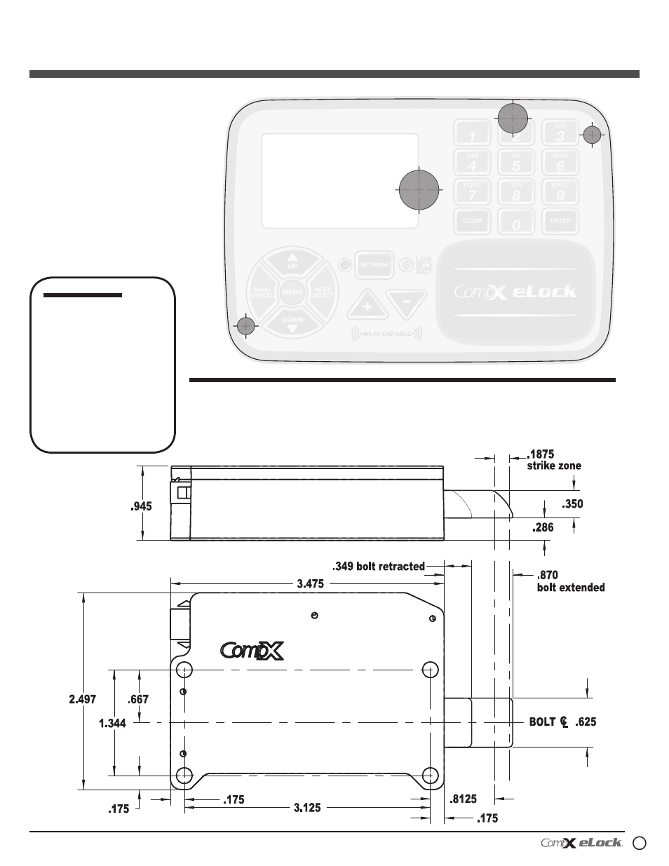
200/300 Series — CompX cabinet eLock Instructions
200 & 300 Series
CompX Cabinet eLock
Controller Mounting Template
Drill
3
/
8
" through
hole only if unit
is Wi-Fi
IMPORTANT: Use template on outside
surface where eLock is to be mounted.
*DRILL FROM THIS SIDE*
w
#1, 2 and 3 are REqUIRED
w #1 and 2 are through holes to mount
the display to the application
w #3 is the through hole to make the
connection between the display and
the interior control module
w #4 through hole is only needed if
the eLock is equipped with wireless
feature (300 Series) “WS-XX-CAB”
Drill ½"
through hole
for cable
#4
#3
Drill
7
/
32
"
through hole
(#2) for
mounting
Drill
7
/
32
"
through hole
(#1) for
mounting
#2
#1
warning:
Print this
page and measure the line
above. It is OnE IncH
LOng. If it measures less
than or more than one inch,
the template measurements
also need to be scaled
accordingly.
Failure to do so
could result in
misdrilled holes.
1"
Screws to be used for mounting
eLock latch:
w 4 –
#
10 x 1½" philips pan head wood
screw for mounting motorized latch
Screws to be used for mounting
eLock controller:
w 2 –
#
10 x ½" philips pan head hi-
low blunt point (type B) SEMS
mounting screw (use on sheet metal
application) – OR –
w 2 –
#
10 x 1
7
/
32
" philips pan head
hi-low blunt point (type B) SEMS
mounting screw (use on MINIMUM
5
/
8
" thick application; do not use
on sheet metal application)
200/300 Series
Cabinet eLock — Installation
200 & 300 Series
CompX Cabinet eLock
Latch Mounting Template