CompX eLock Network Cabinet User Manual
Page 5
5
200/300 Series — CompX cabinet eLock Instructions
200/300 Series
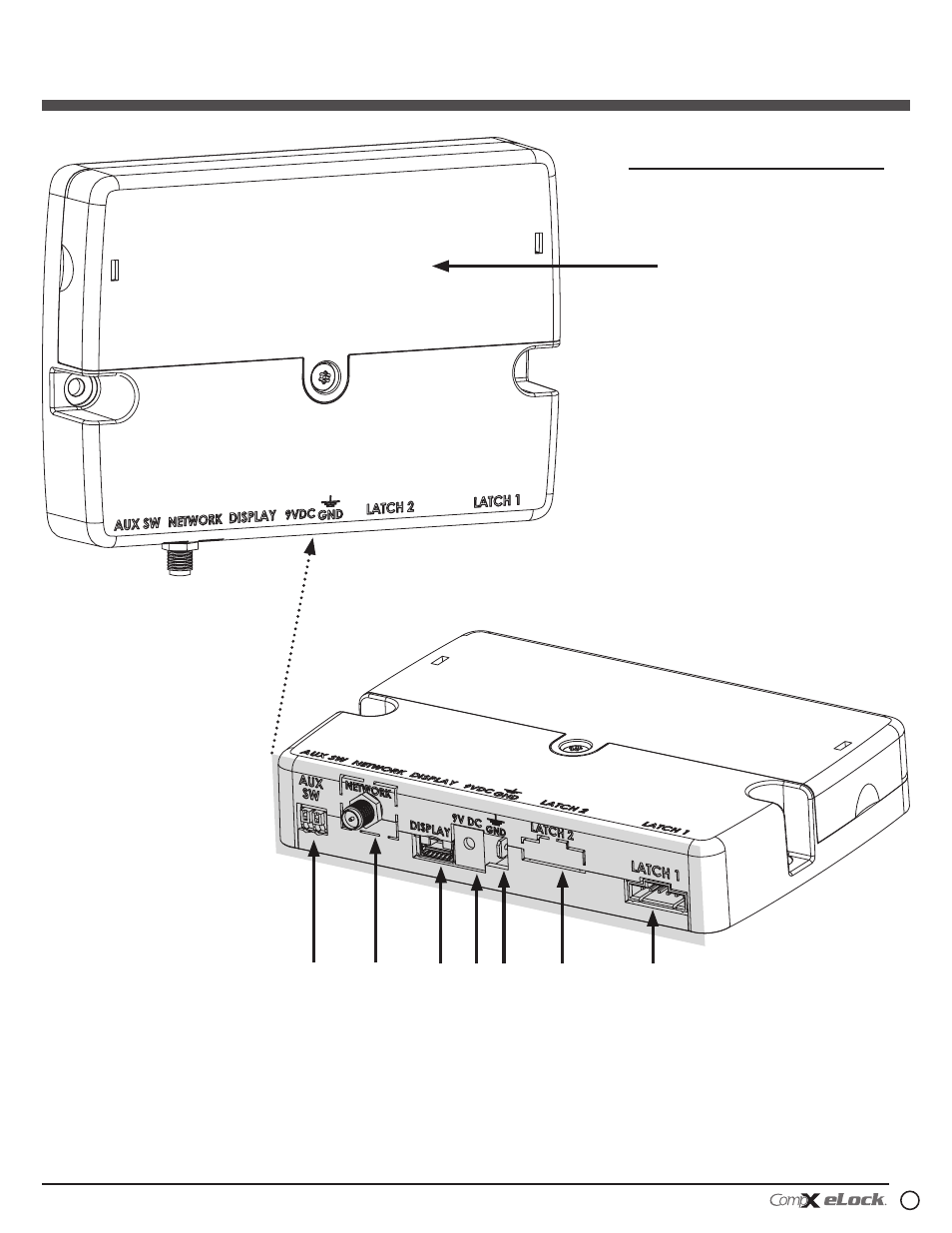
Cabinet eLock — Components
continued
Battery compartment
1
2
3
4 5
6
7
8
1. Door switch connector (door
switch not included)
2. Wi-Fi antenna cable connector
or Ethernet connector (Wi-Fi
connector shown; 300 Series only)
3. Battery cable connector
4. 2.5 mm AC adapter plug-in
(adapter not included)
5. Ground terminal
6. Dual eLatch connector (Latch 2, if
equipped; one latch is included)
7. Latch connector (Latch 1; one
latch is included)
8. Battery pack cover (6-AA batteries
not included)
Screws to be used for mounting eLock
battery compartment:
w 2 – #8 x 5/8” philips pan head wood
screw for mounting battery compartment
Note:
Battery compartment should be mounted
within length of battery cable and latch
cable.