Daktronics M SERIES User Manual
Page 18
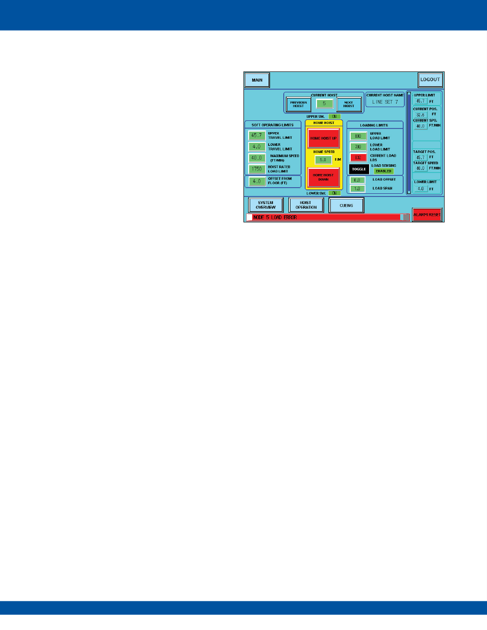
LOADING LIMITS
This is where the LOAD OFFSET and LOAD SPAN are
set up, along with the UPPER/LOWER LOAD LIMITS.
The span is normally set to “1.0” with the offset at “0.0”.
The upper and lower load limits should be set to a range
around the current load. For example if the load is 750
lbs, the upper limit might be set to 800 and the lower
limit to 700.
The CURRENT LOAD reading is displayed and the
LOAD SENSING can be set to ENABLED or DISABLED.
If the load sensing is enabled, the load value will turn
red if the load goes under or over the load limits.
An alarm will appear in the alarm bar (Figure 10).
This will also stop the hoist. It is up to the operator at that
point to see if the batten hung up on something to cause
the load shift. Once the load is back in range, the hoist
will function again, and the load reading will return back
to green.
Upper/Lower Limit Switches
The upper (UPPER SW.) and lower (LOWER SW.) limit
switch status is displayed above and underneath the
home up and down buttons. These should always show
“ON”. If one of the switches is off, then the hoist has
reached a limit switch, and an alarm stating this will be
displayed on the alarm bar.
Figure 10
: Load Sensing Enabled
18